3
General Information
1.3 MP Matrices
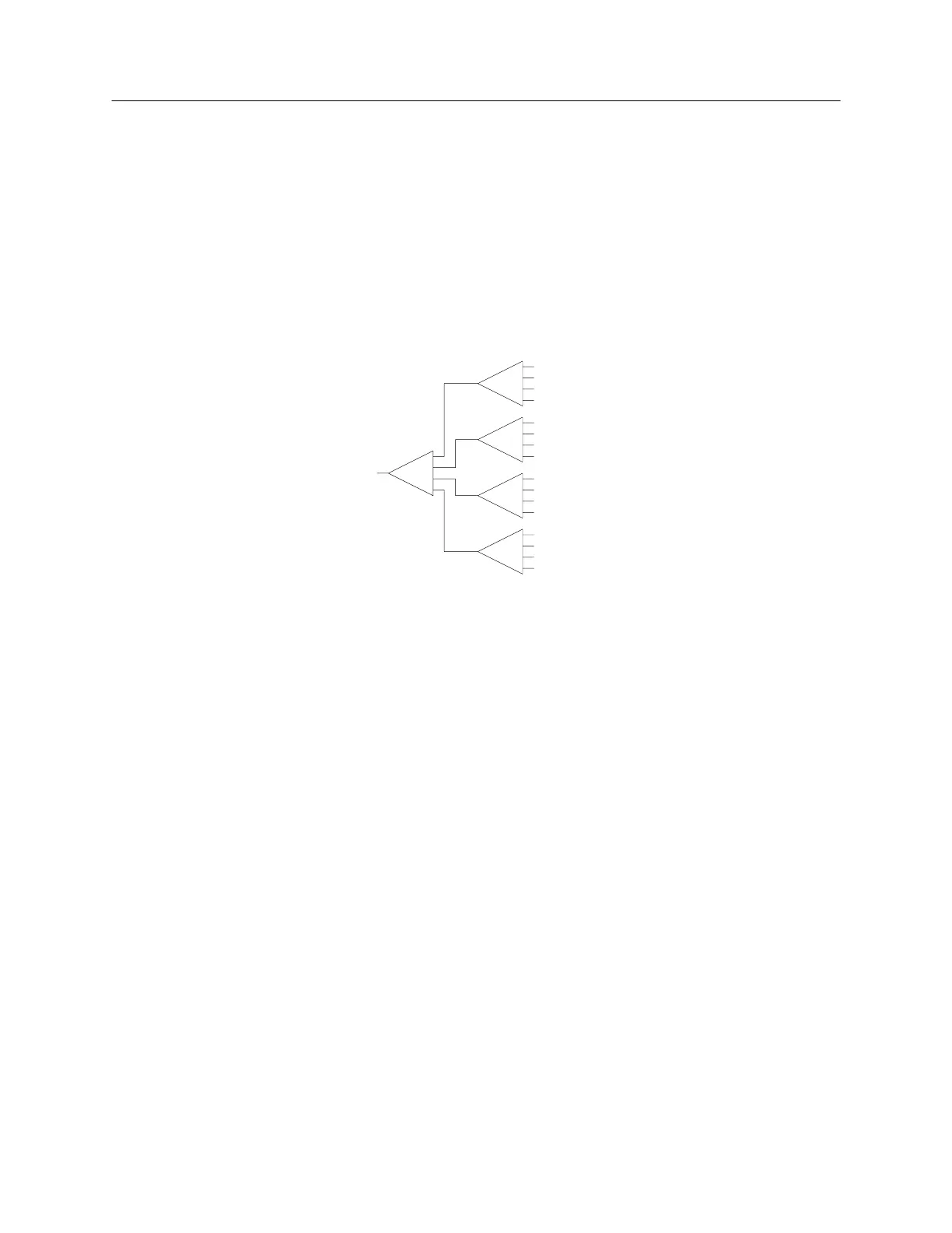
MP-Series stands for Multiplexer. It is a matrix with one input connecting to
many outputs (only one at the time) or, since the RF switches are bi-directional,
many inputs connected to one output (only one at the time).
The switches are populated either on the rear panel or inside the matrix
chassis. From an RF point of view the switches are interconnected and all
input/output RF ports are available to the user on the rear panel of the matrix.
Depending on the size of the switch and the quantities needed, the matrix size
can grow from 1RU to 4RU (or even larger).
Input
SW2
SW1
SW3
SW4
SW5
Out 1
Out 2
Out 3
Out 4
Out 5
Out 6
Out 7
Out 8
Out 9
Out 10
Out 11
Out 12
Out 13
Out 14
Out 15
Out 16
Example of an MP series matrix with 1 input/output and 16 outputs/inputs.
Part Numbering Examples:
MP-4U18S-100-GPIB
A Multi Plex matrix with the following characteristics:
4U, 18 GHz, SMA, 100 outputs, GPIB
MP-4U18S-20- GPIB
A Multi Plex matrix with the following characteristics:
4U, 18 GHz, SMA, 20 outputs, GPIB
MP-[chassis size][frequency][connector]-[number of ports]-[remote control type]
[chassis size]: 1U | 2U | 3U | 4U etc.
[frequency]: 12 (for 12.4 GHz) | 18 (for 18 GHz) | 26 (for 26.5 GHz) | 40 (for 40 GHz)
[connector]: B (for BNC) | N (for N-type) | S (for SMA) | K (for 2.9 mm)
[number of ports]: 20 | 30 | 40 | 50 | 60 | 70 | 80 | 90 | 100 (and more ports if chassis size
allows)
If ports are internally terminated, add ‘T’ to the number.
Example: 20T, .. , 100T
[remote control type]: ENET (for Ethernet, RS-232, USB) | GPIB (for IEEE-488, USB)
Note: There is always one only input and a certain number of outputs. So no need to indicate
the ‘1’ (for the input).
 Loading...