Assembly
6 Requirements
Depending on the suction system, different
installation options are available.
Further information can be found in our
suction planning information leaflet. Order
number9000-617-03/..
6.1 Installation/setup room
The room chosen for set up must fulfil the follow-
ing requirements:
– Closed, dry, well-ventilated room
– Should not be a room made for another pur-
pose (e. g. boiler room or wet cell)
– When installing in a cabinet the inlet and outlet
ventilation slots must be present; minimum
free cross-section at least 120 cm
2
.
– Forced ventilation (fan) must be provided if
there is a risk that the recommended room air
temperature could be exceeded. The air flow
performance must be at least 2 m
3
/min.
– Do not cover cooling slots or openings with
housing installations; ensure sufficient clear-
ance to the openings to permit sufficient cool-
ing.
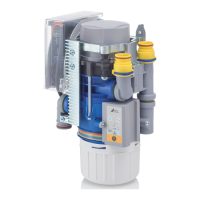
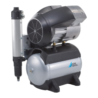
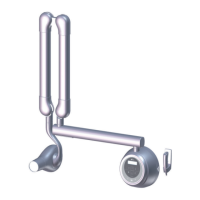
6.2 Setup options
The following options for setting up the unit are
available:
– Wall installation using a Dürr Dental wall
mounting
– In a ventilated cabinet
– In a Dürr Dental noise reducing housing
6.3 Pipe materials
Only use vacuum-sealed HT-waste pipes
manufactured from the following materials:
– Polypropylene (PP),
– Chlorinated polyvinyl chloride (PVC-C),
– Unplasticized polyvinyl chloride (PVC-U),
– Polyethylene (PE).
The following materials must not be used:
– Acrylonitrile-butadiene-styrene (ABS),
– Styrene copolymer blends (e.g. SAN + PVC).
6.4 Hose materials
For waste connections and suction lines only
use the following hose types:
– Flexible spiral hoses made of PVC with inte-
grated spiral or equivalent hoses
– Hoses that are resistant to dental disinfectants
and chemicals
Plastic hoses will display signs of ageing
over time. Therefore, they should be
inspected regularly and replaced as nec-
essary.
The following types of hoses must not be
used:
– Rubber hoses
– Hoses made completely of PVC
– Hoses that are not sufficiently flexible
6.5 Information about electrical
connections
❯
Ensure that electrical connections to the mains
power supply are carried out in accordance
with current valid national and local regulations
and standards governing the installation of low
voltage units in medical facilities.
❯
Install an all-pole disconnect switch with a con-
tact opening width of at least 3 mm in the elec-
trical connection to the mains power supply.
❯
Observe the current consumption of the
devices that are to be connected.
Electrical fusing
LS switch 16 A, characteristic B, C and D in
accordance with 60898.
6.6 Information about connecting
cables
The diameter of the connections depends on the
current consumption, length of line and the ambi-
ent temperature of the unit. Information concern-
ing the current consumption can be found in the
Technical Data supplied with the particular unit to
be connected.
The following table lists the minimum diameters
of the connections in relation to the current con-
sumption:
Current consumption of
unit [A]
Cross-section
[mm
2
]
> 10 and < 16 1.5
> 16 and < 25 2.5
Assembly
26 7119100007L02 1909V001
EN
 Loading...