Current consumption of
unit [A]
Cross-section
[mm
2
]
> 25 and < 32 4
> 32 and < 40 6
> 40 and < 50 10
> 50 and < 63 16
Mains supply cable
Installation type
Line layout (minimum
requirements)
Fixed installation – Plastic sheathed cable
(e.g. type NYM‑J)
Flexible – PVC flexible line
(e.g. H05 VV‑F)
or
– Rubber connection
(e.g. H05 RN‑F or
H05 RR‑F)
Control cable
24 V protective low voltage for:
– Hose manifold
– Place selection valve
– Spittoon valve
Installation type
Line layout (minimum
requirements)
Fixed installation – Shielded sheathed cable
(e.g. (N)YM (St)-J)
Flexible – PVC data cable with
shielded cable sheath-
ing, as used for
telecommunications and
IT processing systems
(e.g. type LiYCY)
or
– Lightweight PVC control
cable with shielded
cable sheathing
7 System components
The system components listed below are
required or recommended for various procedures
or for installation.
7.1 Rinsing unit
It is recommended that the suction system is
equipped with a rinsing unit, e.g. in the treatment
unit. The rinsing unit provides a small amount of
water during aspiration. This dilutes the aspirated
fluids (blood, saliva, rinsing water etc.), which can
then be transported more effectively.
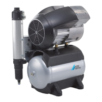
7.2 Flow accelerator
In order to keep the suction system free of
deposits, a flow accelerator can be fitted in con-
junction with a spittoon valve. When using a bowl
rinse system, water will collect before the flow
accelerator. The next time suction takes place
using the large cannula, the collected fluid is
transported in surges and at high speed to the
suction system. This ensures automatic cleaning
of the suction pipes.
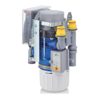
7.3 Amalgam separator
The amalgam separator is designed to separate
out and trap the heavy metal particles and amal-
gam dust that the suction unit aspirates from
drilled fillings. The amalgam separator is installed
in the drain behind the separation unit of the suc-
tion unit. The amount of fluid coming from the
suction unit must not exceed the maximum per-
mitted quantity of fluid that can be handled by
the amalgam separator. Depending on the instal-
lation and on national regulations, a second
amalgam separator may need to be installed.
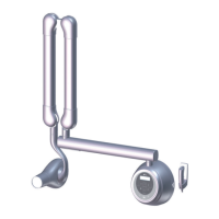
7.4 Surge tank
If the suction unit is combined with an amalgam
separator, this requires the installation of a surge
tank. The surge tank reduces pressure peaks
caused by the waste water pump of the suction
unit and acts as a buffer against temporary rises
in the volume of water.
The surge tank can also be used if the waste
water is fed directly into the building waste water
system. this case the waste water from the suc-
tion unit is diverted to the building drainage sys-
tem under zero pressure.
Assembly
7119100007L02 1909V001 27
EN
 Loading...