UPS SYSTEM INSTALLATION
Eaton 9395 UPS (450–825 kVA) Installation and Operation Manual S 164201725 Rev 4 www.eaton.com/powerquality
4-19
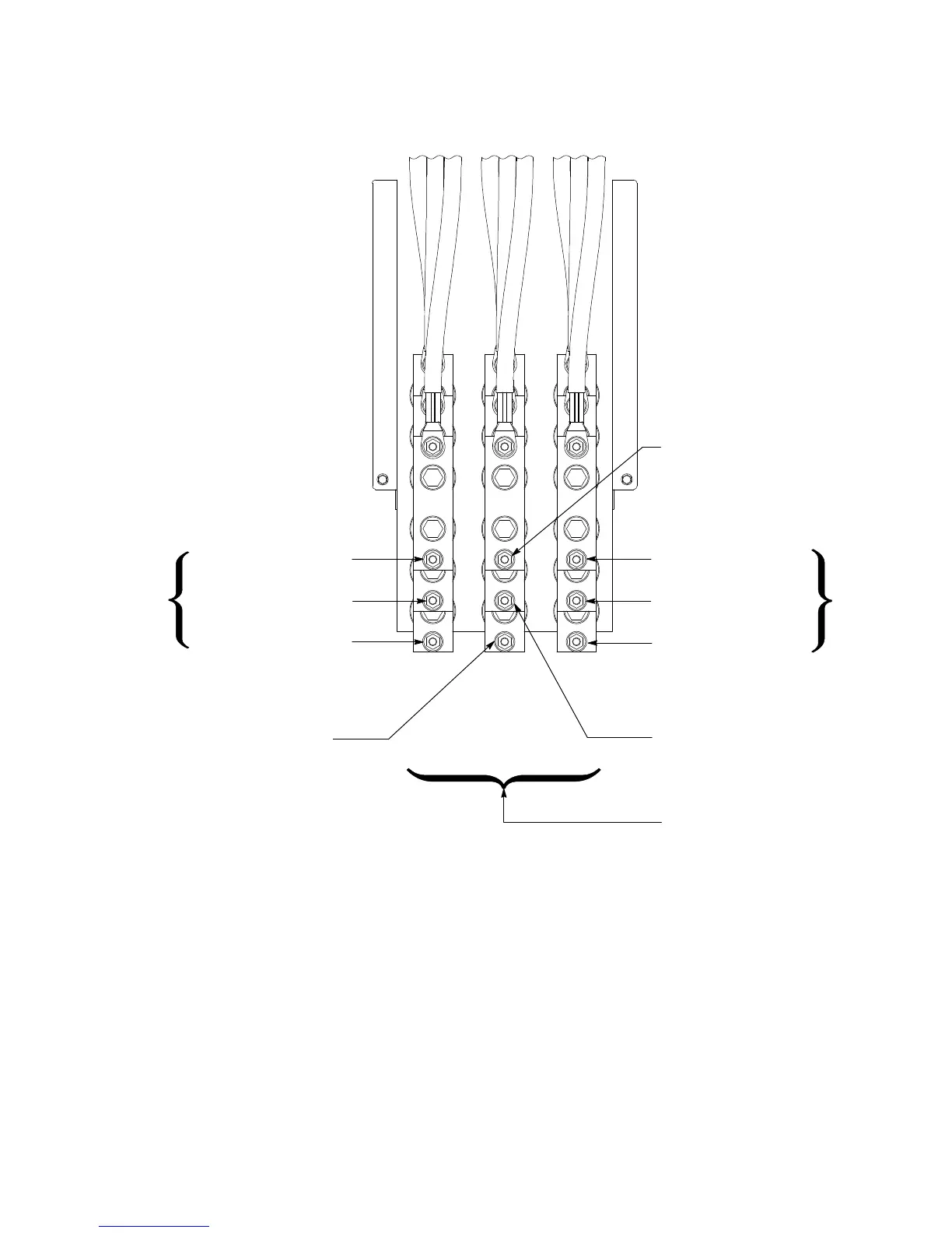
UPM 1 Cable 1G1 & 1G2 Yellow
Phase C (E3A)
UPM 2 Cable 2G1 & 2G2 Yellow
UPM 3 Cable 3G1 & 3G2 Yellow
UPM 1 Cable 1G1 & 1G2 Orange
Phase A (E1A)
UPM 2 Cable 2G1 & 2G2 Orange
UPM 3 Cable 3G1 & 3G2 Orange
AC Input to UPMs
UPM 1 Cable 1G1 & 1G2 Brown – Phase B (E2A)
UPM 2 Cable 2G1 & 2G2 Brown – Phase B (E2A)
Phase B (E2A) – UPM 3 Cable 3G1 & 3G2 Brown
NOTE Two cable lugs will be connected to each terminal stud. When connecting the cable lugs, install the first lug on the stud with the raised
barrel portion facing the back of the cabinet. Install the second lug with the raised barrel portion facing the front of the cabinet.
NOTE On a UPS without CB1, UPM input wiring terminations are in the same positions on the bus bars installed in the place of CB1.
NOTE On a UPS configured as an Input Output Module (IOM), UPM input wiring terminations are the same as an ISBM configuration.
Phase A
Phase B Phase A
(Not used with Two UPM systems.)
(Not used with Two UPM systems.)
(Not used with Two UPM systems.)
Figure 4‐15. ISBM Section Input Power Terminal Detail – Separate Rectifier Feed, Momentary Static Switch
 Loading...