UPS SYSTEM INSTALLATION
Eaton 9395 UPS (450–825 kVA) Installation and Operation Manual S 164201725 Rev 4 www.eaton.com/powerquality
4-20
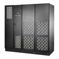
DC Input to UPMs
+
Cable 1G3 Black
UPM 1 (1E5A)
Cable 1G3 Black
DC Input to UPMs
Cable 1G3 Red
UPM 1 (1E4A)
Cable 1G3 Red
–
Cable 2G3 Black
UPM 2 (2E5A)
Cable 2G3 Black
Cable 3G3 Black
UPM 3 (3E5A)
Cable 3G3 Black
+
+
+
–
–
–
Cable 2G3 Red
UPM 2 (2E4A)
Cable 2G3 Red
Cable 3G3 Red
UPM 3 (3E4A)
Cable 3G3 Red
(Not used with Two UPM systems.)(Not used with Two UPM systems.)
Figure 4‐16. ISBM Section Battery Input Power Terminal Detail
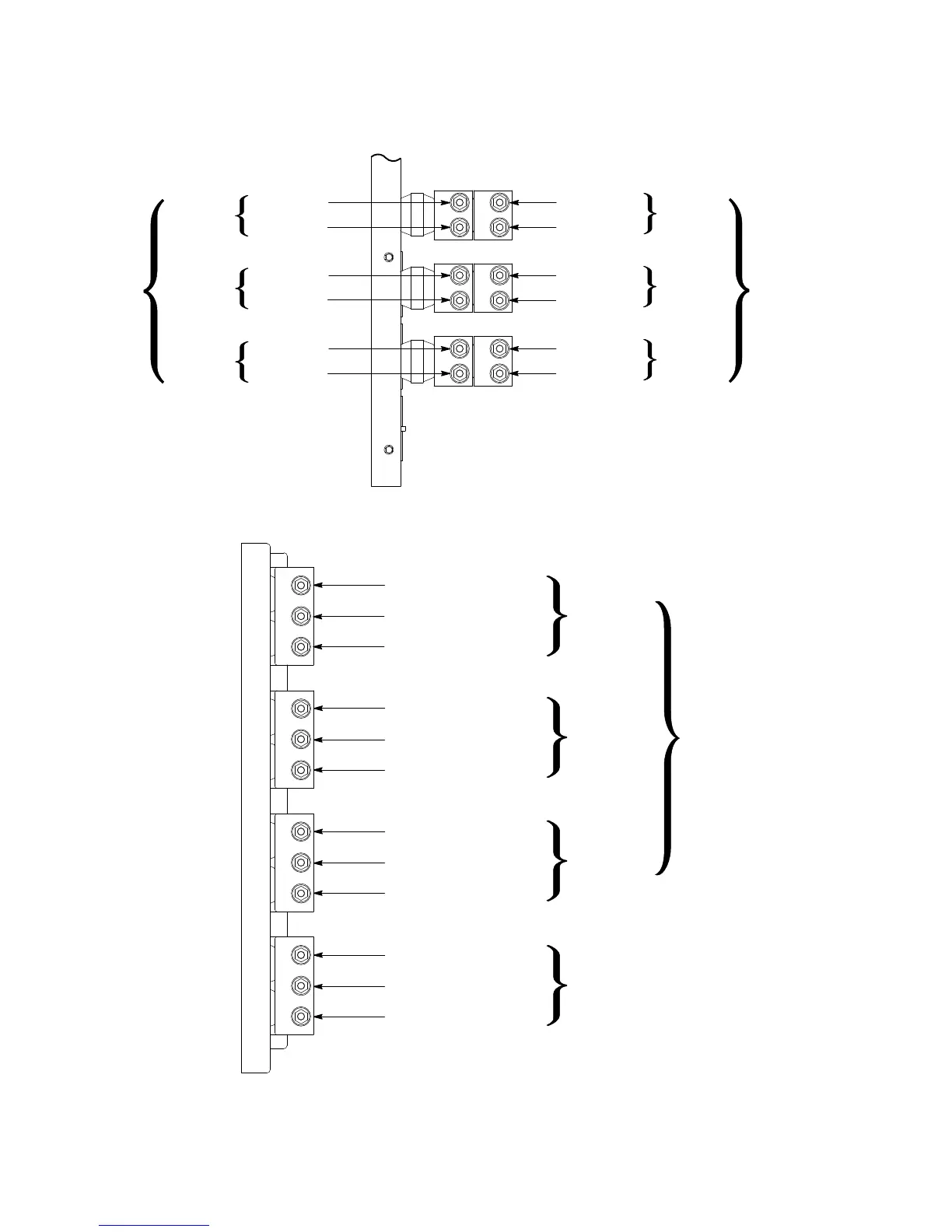
AC Output
from UPMs
UPM 1 Cable 1G4 & 1G5 Orange
Phase A (E9A)
UPM 2 Cable 2G4 & 2G5 Orange
UPM 3 Cable 3G4 & 3G5 Orange
UPM 1 Cable 1G4 & 1G5 Brown
UPM 2 Cable 2G4 & 2G5 Brown
UPM 3 Cable 3G4 & 3G5 Brown
UPM 1 Cable 1G4 & 1G5 Yellow
UPM 2 Cable 2G4 & 2G5 Yellow
UPM 3 Cable 3G4 & 3G5 Yellow
UPM 1 Cable 1G4 & 1G5 Gray
UPM 2 Cable 2G4 & 2G5 Gray
UPM 3 Cable 3G4 & 3G5 Gray
Phase B (E10A)
Phase C (E11A)
Neutral from
UPMs (E12A)
NOTE Two cable lugs will be connected to each terminal stud. When connecting the cable lugs, install the first lug on the stud with the raised
barrel portion facing the back of the cabinet. Install the second lug with the raised barrel portion facing the front of the cabinet.
(Not used with Two UPM systems.)
(Not used with Two UPM systems.)
(Not used with Two UPM systems.)
(Not used with Two UPM systems.)
Figure 4‐17. ISBM Section Output Power Terminal Detail
 Loading...