UPS System Installation
4-12 Eaton 93E UPS (300/400 kVA, 380/400/415V) Installation and Operation Manual
c. Supporting the top rear panel at the back of the cabinet, reconnect the fan connectors to the wiring
harnesses.
d. Reinstall the top rear panel by tilting into position and securing the panel using the retained hardware.
e. Reinstall the power terminal cover top using the retained hardware.
f. Install the power terminal cover right and left sides using the provided hardware.
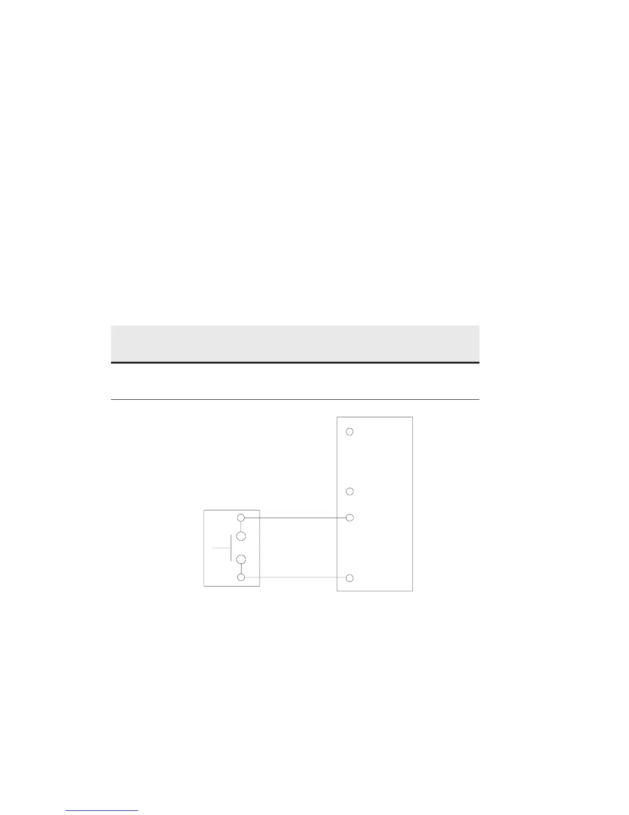
5. Connect the wiring as shown in Table 4-4 and Figure 4-8 for a normally-open REPO or Table 4-5 and
Figure 4-9 for a normally-closed REPO.
6. If using a normally-closed REPO switch, connect a jumper wire between pins 3 and 4 on the REPO
terminal block.
7. If you are installing multiple REPO switches, wire additional switches in parallel with the first REPO.
8. If required, install wiring from the REPO switch to the trip circuitry of the upstream protective devices. A
second contact block is provided on the REPO switch for this function . The REPO switch wiring must be in
accordance with local regulations.
9. Reinstall the interface terminal cover using the retained hardware.
Table 4-4. REPO Connections
From REPO Station(s)
Switch Contact Block
(Either Block)
To REPO Terminal Block
on Back of UPS Cabinet Wire Size Tightening Torque
3 NO 3 Twisted Wires (2)
14-22 AWG
(0.75 -4.0 mm
2
)
7 lb in
(0.8 Nm)
Figure 4-8. Normally-Open REPO Switch Wiring
3
1
2
4
3
4
REPRO
Switch
(No)
Twisted
Wires
REPO TB
 Loading...


