Figure 23. Communication interfaces
1. X9 External parallel interface
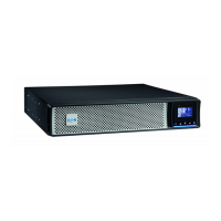
Figure 24. X9 External parallel interface
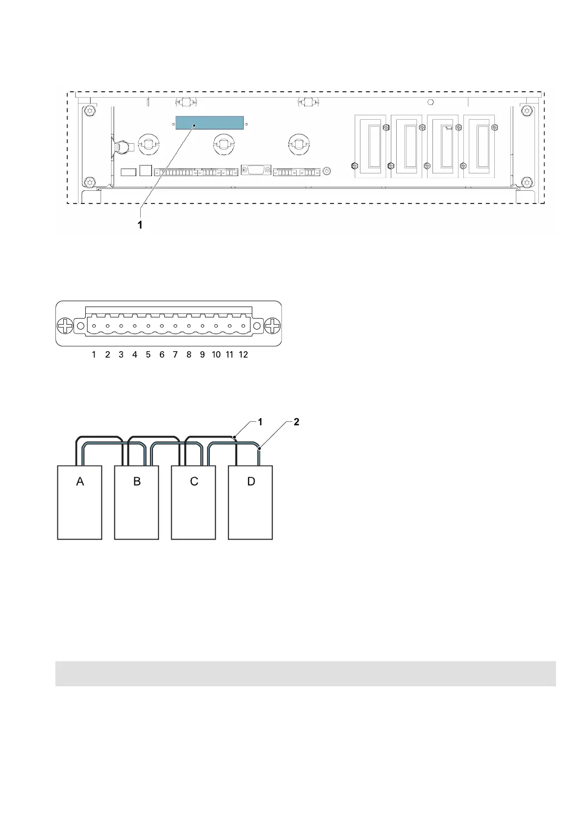
Figure 25. Simplified CAN and Pull-Chain wiring for parallel UPS system
A UPS 1 1 CAN
B UPS 2 2 Pull chain
C UPS 3 (if installed)
D UPS 4 (if installed)
NOTE: This drawing is for distributed bypass wiring purposes and it is not a floor layout plan. UPSs can be
placed in any physical order.
EATON 93PM G2 UPS USER’S AND INSTALLATION GUIDE P-164000956
-
February 2021 www.eaton.eu 5588
 Loading...