Understanding UPS Operation
5-6 Eaton 93PM UPS (20–50 kW, 480V Four Wire – 50 kW Frame) Installation and Operation Manual P-164000540—Rev 4 www.eaton.com/powerquality
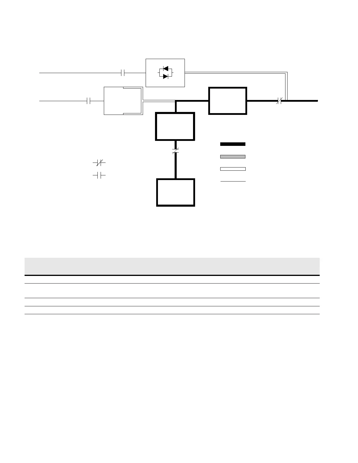
Figure 5-5. Path of Current Through the UPS in Battery Mode
5.3 Single UPS Unit System Oneline Configurations
The system oneline drawings in this section show the simplified internal structure of the UPS, battery supply,
and basic maintenance bypass.
Bypass Input
Static
Switch
Bypass Switchgear
Rectifier
Inverter
Inverter
Switchgear
Rectifier
Switchgear
Rectifier Input Output
Battery Converter
Battery
Switchgear
Main Power Flow
Switchgear
Closed
Open
Battery
Trickle Current
De-Energized
Energized
Oneline Drawing UPS Model
Voltage
System TypeInput Output
See Figure 5-6 93PM-50-1 480 480 Single one UPM reverse transfer UPS
with internal battery
See Figure 5-7 93PM-50-1 480 480 Single one UPM reverse transfer UPS
with internal and
external batteries
See Figure 5-8 93PM-50-1 480 480 Single one UPM reverse transfer UPS
with external battery
See Figure 5-9 93PM-50-2 480 480 Single two UPM reverse transfer UPS
with external battery
 Loading...


