Understanding UPS Operation
Eaton 93PM UPS (20–50 kW, 480V Four Wire – 50 kW Frame) Installation and Operation Manual P-164000540—Rev 4 www.eaton.com/powerquality 5-9
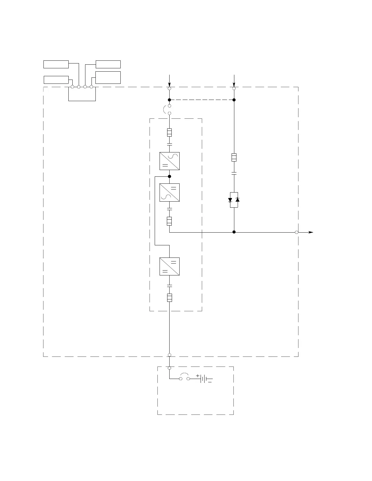
Figure 5-8. Eaton 93PM-50-1 UPS System Oneline with External Battery
Optional Single-Feed
Jumper
E4, E5
E1, E2, E3 E6, E7, E8, E12
Parallel CAN
Mini-Slot
Interface
Interface
Board
Pull Chain
Remote EPO
AC Input to
Bypass 4 Wire
A-B-C Rotation
AC Input to UPS
Rectifier 3 Wire
A-B-C Rotation
A
B
AC Output to
Critical Load
D
UPS CABINET
E9,
E10,
E11,
E12
Bypass
Switchgear
Static
Switch
Fuse
UPM 1
Battery
Switchgear
Battery
Converter
Fuse
Rectifier
Fuse
Rectifier
Switchgear
Fuse
Inverter
Inverter
Switchgear
CB1 Input
Breaker
NOTE Callout letters A, B, and D map to Table 3-4.
Battery
Breaker
(Not supplied with the UPS)
C
EXTERNAL BATTERY
CABINET
 Loading...


