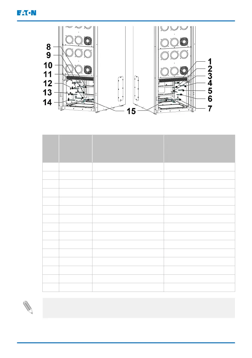
Figure 17. Transformer cabinet power terminals
Reference Transformer cabinet with
input and output
transformers
Transformer cabinet with
rectifier and bypass input
transformers
1 X3:L1 From UPS output L1 Bypass input L1
2 X3:L2 From UPS output L2 Bypass input L2
3 X3:L3 From UPS output L3 Bypass input L3
4 X4:L1 System output L1 To UPS bypass input L1
5 X4:L2 System output L2 To UPS bypass input L2
6 X4:L3 System output L3 To UPS bypass input L3
7 X4:N System output N To UPS bypass input N
8 X1:L1 System input L1 Rectifier input L1
9 X1:L2 System input L2 Rectifier input L2
10 X1:L3 System input L3 Rectifier input L3
11 X2:L1 To UPS input L1 To UPS rectifier input L1
12 X2:L2 To UPS input L2 To UPS rectifier input L2
13 X2:L3 To UPS input L3 To UPS rectifier input L3
14 X2:N To UPS input N To UPS rectifier input N
15 PE Protective earthing Protective earthing
Note: For information on the internal wiring of the transformer cabinet, see the
Site planning data of TFC-A.
Follow these steps to install transformer cabinet power wiring.
Eaton 9PHD Accessory Cabinets TFC-A, EBC-F
and EBC-G User's and installation guide
©
Eaton Corporation plc 2022. All rights reserved. Document ID: P-164000538 49 (63)
 Loading...