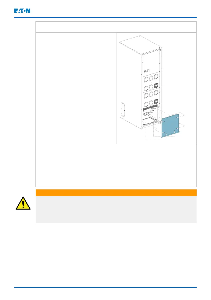
1. Open the cabinet door.
2. Open the screws on the lower
front panel.
3. Remove the lower front panel.
4. Route the power cables through the through hole of your choosing. See
Figure
16
for more information.
5. Apply suitable protection to protect the wiring from the sharp metal
edges.
6. Connect the power cables to the connectors according to Figure
17
.
7. Put the front plate back and fasten the screws.
WARNING
The transformer cabinet does not have neutral to ground bonding. Where
such bonding is required, it must be done separately in the power terminals of
the transformer cabinet. Note that it’s not allowed to bond the neutral to
ground in an UPS system without isolation transformers.
Eaton 9PHD Accessory Cabinets TFC-A, EBC-F
and EBC-G User's and installation guide
©
Eaton Corporation plc 2022. All rights reserved. Document ID: P-164000538 50 (63)
 Loading...