3.7.2 How to install transformer cabinet signal wiring
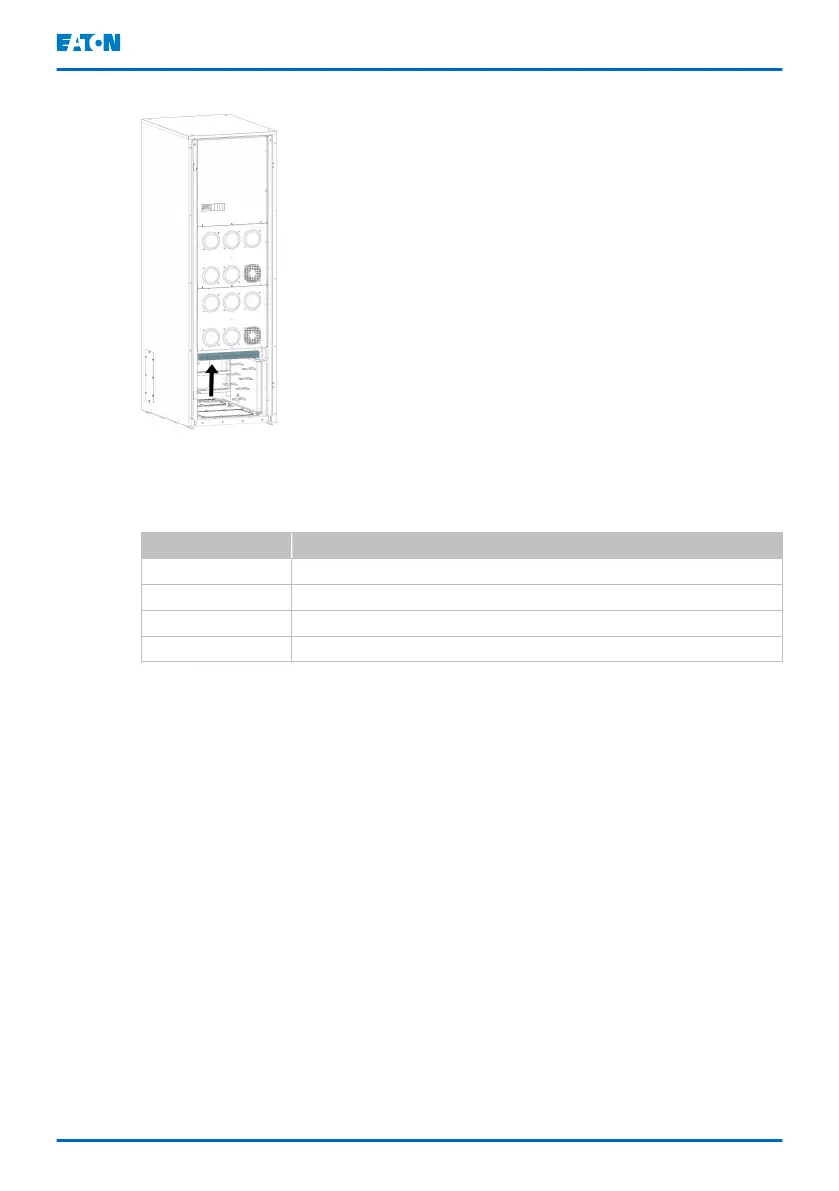
Figure 18. Location of transformer cabinet signal terminals
Table 11: Transformer-to-UPS signal terminals (terminal X5)
Pin Pin function
X5:1 Over temperature
X5:2 Over temperature return
X5:3 Fan failed
X5:4 Fan failed return
The signal wires are routed from the transformer cabinet to the UPS. The
transformer cabinet has 2 signals.
• Transformer over temperature signal
This signal alarms the UPS that the transformer has exceeded its operating
temperature range, and if the issue persists, the UPS will shut down after a
delay.
• Fan failure signal
This signal is generated, if one or more fans no longer rotate at the desired
speed.
The signal outputs of the transformer cabinet are located in the signal terminal
block X5. Refer to Table
11
for the pin assignments.
Follow these steps to install transformer cabinet signal wiring.
1. Connect the transformer over temperature alarm (transformer cabinet
terminals X5:1–X5:2) to the UPS cabinet’s signal inputs (UPS terminals
X10:1–X10:10, valid for 9PHD only).
• Any free signal input in the UPS can be used for this purpose.
Eaton 9PHD Accessory Cabinets TFC-A, EBC-F
and EBC-G User's and installation guide
©
Eaton Corporation plc 2022. All rights reserved. Document ID: P-164000538 51 (63)