17
Instruction Booklet IB 33-790-1J
Effective November 2010
Instructions for Low Voltage Power
Circuit Breakers Types DS and DSL
EATON CORPORATION www.eaton.com
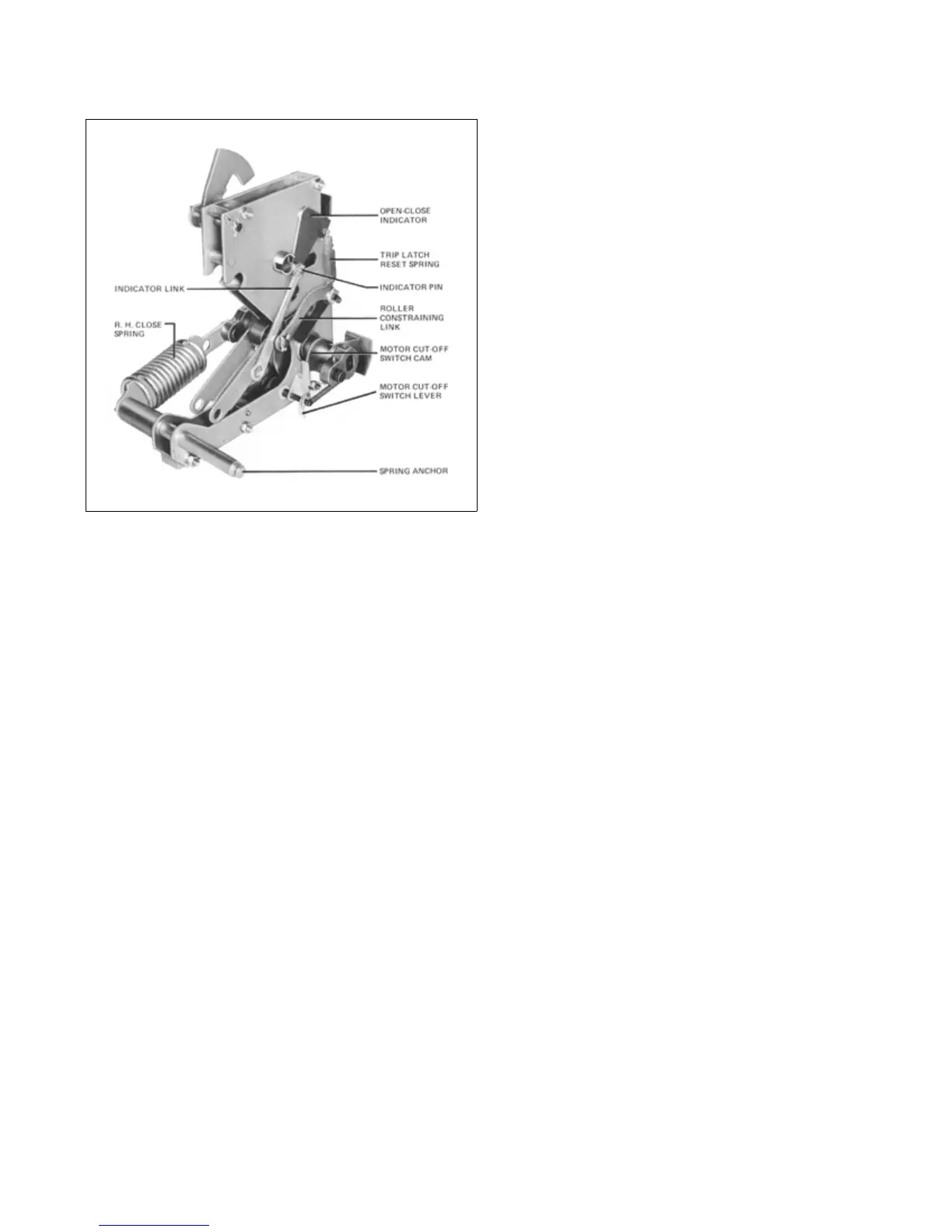
Fig. 13 Rear View of Mechanism (Left Close Spring
Removed).
5.1.1 Power-Operated Mechanism
In the power-operated version, the mechanism is
equipped with a universal-type motor for automatic
charging of the closing springs. It is equipped with a
spring release device for electrically closing through a
control switch pushbutton, or other circuit-making device.
A shunt trip device is supplied for remote tripping through
a control switch, relay, etc. In the absence of control
volt-
age, or whenever desirable, the closing spring ca
n be
charged by hand with the emergency charging handle.
Hand closing of the breaker can be done by means of the
close bar. Hand opening of the breaker can be done by
means of the trip plate.
5.1.2 Explanation of Spring-Charging Mechanism for
Power-Operated Breakers
Figure 14 is an isometric diagram of the principal parts of
a completely power-operated mechanism.
Figure 15 is a front view drawing sho
wing the principal
parts of the spring-charging port
ion of this mechanism.
Other parts are omitted for clarity. Figures 16a and 16b
show in greater detail the major parts of the spring-charg-
ing mechanism in the two basic positions:
Closing springs charged (16a); and
Closing springs discharged (16b).
Referring to Figure 15, the basic elements are mounted
on the crank shaft (8). This is a straight shaft with four
flats machined on it, and a crank arm (11) attached
to
each end. Each crank arm connects to its closing spr
ing
(9) by a formed spring end (10) Figure 16b. The rear of
the springs anchor to the rear of the mechanism frame.
The crank arms (11), motor cutoff switch cam (7), close
cam (6) and two drive plates (25) have matching flats;
and are thus anchored to the crank shaft. The spring
charge indicator (12) ratchet wheel (17), oscillator (30),
and emergency charge device (26) do not have internal
flats but ar
e mounted on separate bushings and are free
to rotate on the
crank shaft.
Figure 17 is an exploded view of the crankshaft parts.
Figure 16a is a view looking into the right end of the
crankshaft, and shows the position of the components
when the springs are charged.
Figure 16b is a partial view with the springs discharged.
The motor crank shaft assembly (29), carrying a roller for
driving the oscillator, is pivoted in the right hand mecha-
nism side frame. The hold
pawl (18) is mounted by
means of a pin on the mechanism
side frame as shown.
In operation, rotation of the motor crank pushes the oscil-
lator arm counterclockwise to make the oscillator pawl
(28) push a tooth in the ratchet wheel (17) and rotate the
ratchet wheel slightly more than one tooth in the counter-
clockwise direction. The holding pawl snaps behind the
corresponding advanced tooth, and holds it against the
torque of the closing springs while the oscillator
arm
rotates back clockwise to catch another ratchet tooth.
Thus the ratchet wheel is rotated counterclockwise until
the ratchet wheel pin (21) engages the two drive plates
(25) which in turn rotate the crank shaft and the crank
arms in the same direction until the arms are slightly past
horizontal dead center. Since the close cam (6) is rigidly
mounted on the crank shaft, the same as the drive plates,
it has rotated the same amount as the plates. The close
cam carrie
s a stop roller as shown in Figure 22b. Just
after
horizontal dead center of the crank arms is reached,
the torque of the closing springs starts to rotate the
crank, independently of the driving motor. However, the
stop roller on the close cam quickly stops the movement
of the crank at only a few degrees over center and holds
it there by coming against the spring release latch. This is
the “spring charged” position. The motor cut-off switch
cam
(7) operates the switch (15) through a lever (13) at
th
is time, and the motor stops.
At the instant that the springs snap over dead center, the
lobes of the drive plates raise the pawl lifters (27), and
 Loading...


