33
Instruction Booklet IB 33-790-1J
Effective November 2010
Instructions for Low Voltage Power
Circuit Breakers Types DS and DSL
EATON CORPORATION www.eaton.com
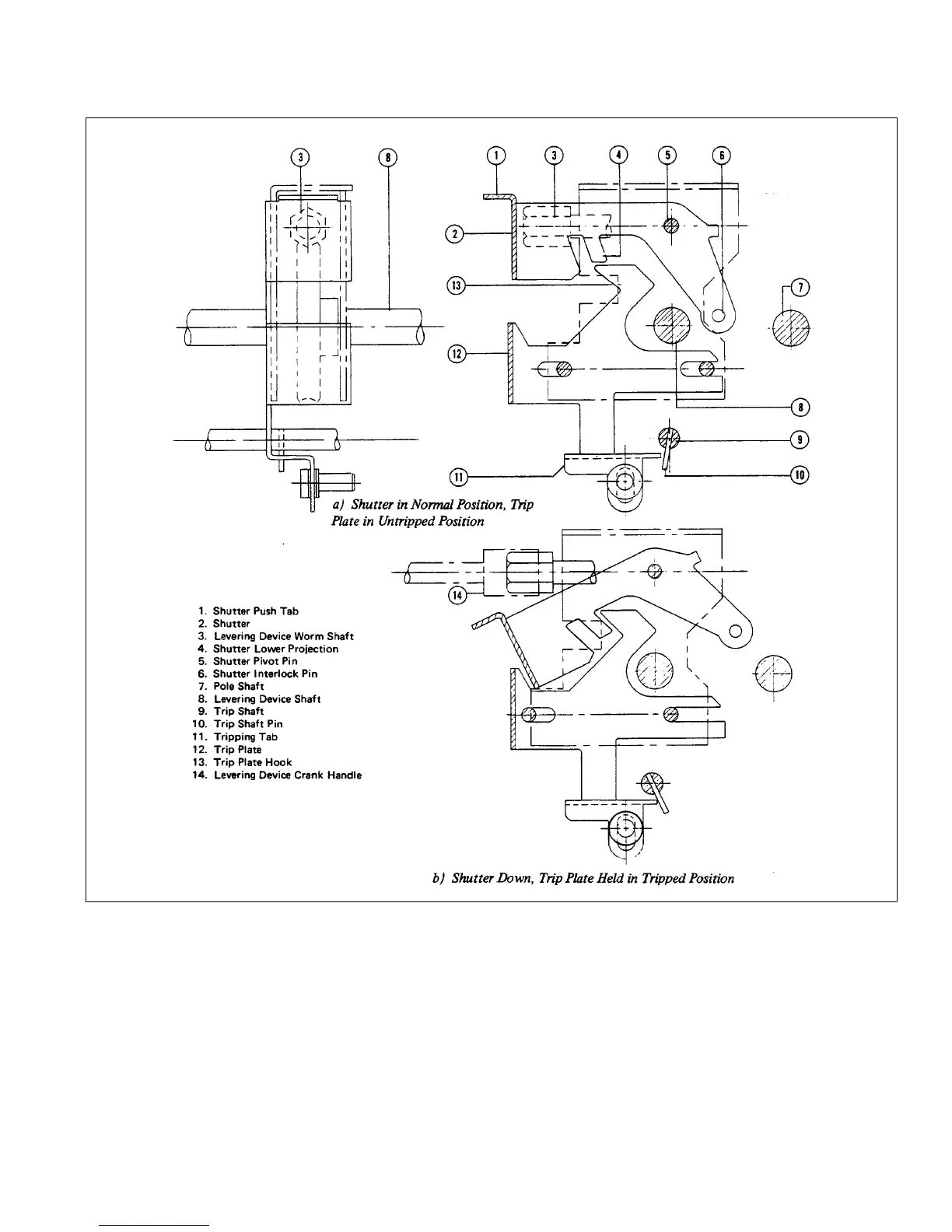
Fig. 28 Relation of Shutter, Trip Plate, and Trip Shaft.
Figure 29d shows the REMOVE position. Here the inter-
lock cam stops with the shutter interlock pin blocked.
Thus the shutter stays down and the breaker stays
tripped when the crank handle is removed. The breaker is
held trip-free, so it cannot be closed. Also, by another
interlock described later, the close-release latch cannot
be released.
5.1.8.1 Spring Discharge Interlock
1. The purpose of this interlock is to operate the
close-release latch as the breaker is moved out
beyond TEST position. This causes a trip-free opera-
tion of the closing mechanism because it occurs
while the levering device crank handle is necessarily
still on the worm shaft, and the closing springs are
charged if the breaker is electrically operated. This is
 Loading...


