80
Instruction Booklet IB 33-790-1J
Effective November 2010
Instructions for Low Voltage Power
Circuit Breakers Types DS and DSL
EATON CORPORATION www.eaton.com
Factory settings are adjustments which should only be
necessary when parts are reassembled after disman-
tling. These are described in Sections 12.2.1 and 12.2.2.
Maintenance adjustments should be made as indicated
on maintenance inspections and are described in Section
12.2.3.
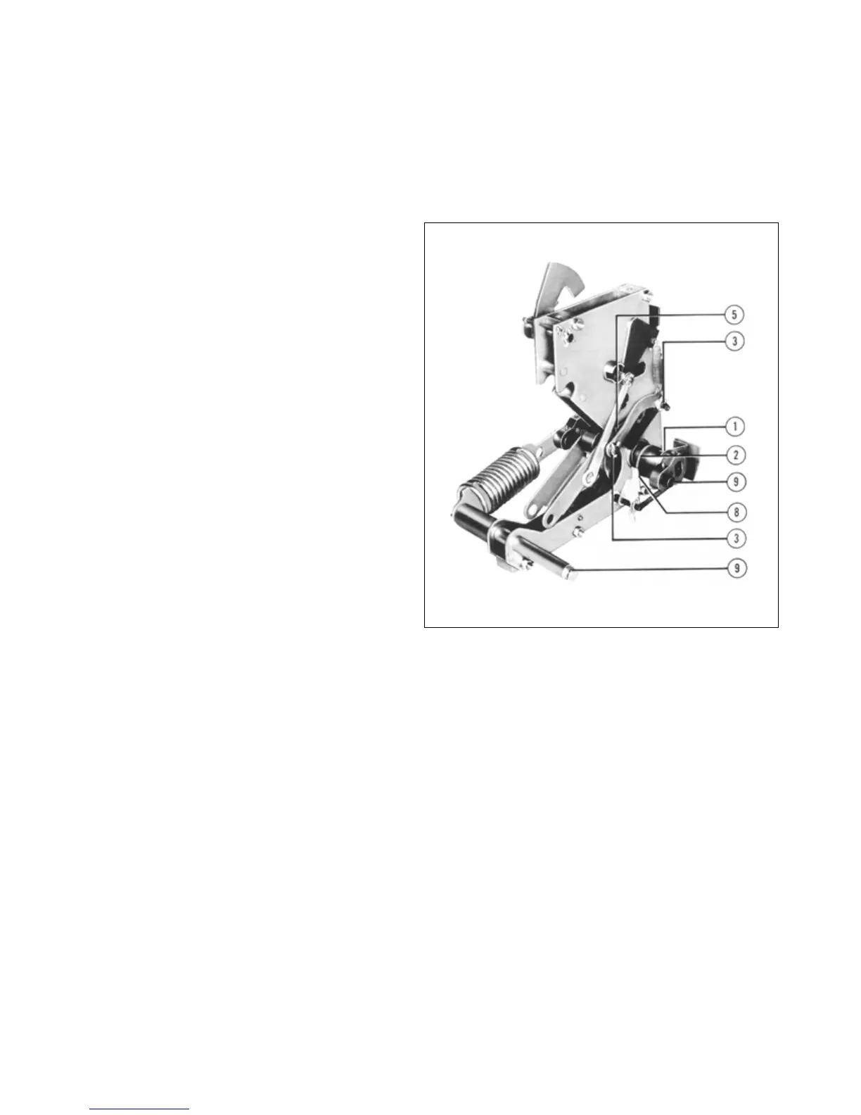
12.2.1 Trip Latch Overlap
Figure 23a shows a composite view of the shunt trip lever
and the trip latch, as described in Section 5.1.6. The angu-
lar position of the trip shaft latch surface is
adjustable in
relation to the trip latch surface by means of a screw
located in the top of the actuator frame. (Figure 23b).
Proper adjustment procedure is as follows.
Close the breaker.
Slowly rotate adjusting screw clockwise until the breaker
trips. This is “no overlap” position.
Rotate adjusting screw 4 turns in a counterclockwise
direction.
12.2.2 Breaker Open Position Stop (DS-632 Only)
Proper Adjustment Procedure is as follows.
Refer to Figure 88.
With
the breaker open, loosen the open position stop bolt
nuts so that the eccentric cylinders can be turned by
hand but will stay put.
Rotate the cylinders to obtain a clearance of approxi-
mately .005 in. between the cylinders and the stop levers.
Tighten nuts on bolts.
12.2.3 Moving Contact Adjustment
The contact assemblies are adjustable for the amount of
engagement only. The lead of the arcing contacts over
the main contacts is fixed. The correct engagement of the
contacts is achieved when the vert
ical faces of the main
fixed contacts and the fixed contact cage are parallel.
For the DS-206 this is obtained by the adjusting nuts
located on the insulating link stud above and below the
pivot block. Refer to Figures 37 and 38. These nuts are
self-locking, and must be tight when the adjustment is
complete.
The moving pole of the DS-416/420 is adjusted by rotat-
ing the insulating link after the lock nut has been loos-
ened (Refer to Figure 39). Tighten the locknut secure
ly
after the adjustment has been completed.
The DS-632 and DS-840 have two adjusting studs on
each pole, and both must be moved together to retain the
parallelism (refer to Figures 43 and 45). A spring type
locking clip holds the adjustment for DS-632. For DS-840
locking nuts similar to DS-416/420 hold the adjustments.
Check contact system as described in Section 12.1.2.
Fig. 90 Lubrication Points on Left Side of Mechanism.
12.2.4 Levering Mechanism
The complete levering mechanism is shown in detail in
Figure 89. If the traveling stop nut on the rear of the worm
shaft has been removed, it must be replaced in the exact
position with respect to the worm gear position for proper
interlock operation. This is achieved when the threaded
worm shaft bottoms in the stop nut and the interlock cam
is in the connected position shown in Figure 29a. The
shutter interlock pin will then drop to
its normal position
beneath the lobe of the cam.
The retaining clamp ring
also operates the position indicator and may be slipped in
its groove in the stop nut. The stop nut is prevented from
rotating by having a “flat” against the bottom of the
breaker horizontal top pan.
When reassembling, care must be exercised to insure
that the two guide spacers are located in the slots of the
 Loading...


