28
Instruction Booklet IB 33-790-1J
Effective November 2010
Instructions for Low Voltage Power
Circuit Breakers Types DS and DSL
EATON CORPORATION www.eaton.com
The trip shaft can be rotated to trip the breaker in the fol-
lowing ways.
1. By hand push on the trip plate. As shown in Figure
27, this item has a tab which pushes against a pin on
the trip shaft which applies a direct rotating force on
the shaft in the tripping direction.
2. By shunt trip device, as shown in Figure 23a. The
armature of the clapper-type electro magnet pushes
on a lever on the trip shaft to rotate it in the tripping
direction.
3. By action of the
actuator, as shown in Figure 24b. A
downward pull by the trip plunger pulls on a lever
from the trip shaft to rotate it in the tripping direction.
4. By action of the trip plate on the front of the breaker
compartment door (providing the breaker is in the
connected position.) A flap on the breaker compart-
ment hinged door, operating through a sliding link
and lever fastened to the cradle move the compart-
ment trip lever extending from the bottom
of the dra-
wout unit. Refer to Figures 25 and 26.
5. An undervoltage trip device is available as an acces-
sory, and will directly operate the trip shaft. This is
shown in Figures 67 & 68, and its operation is cov-
ered in Section 8.7.1.
6. Blown Limiter Indicator. See Fig. 80.
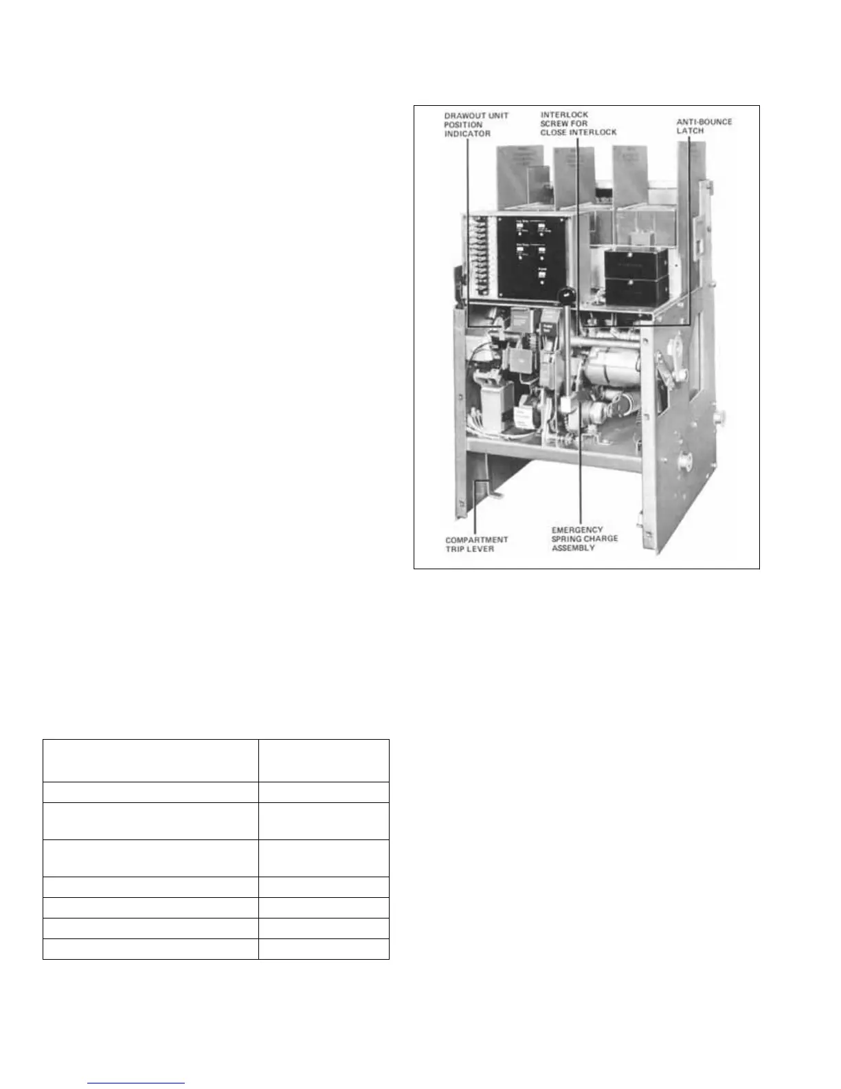
5.1.6.1 Miscellaneous Details
Figure 26 shows a bottom view of the breaker drawout
unit. Visible in this picture are details as follows.
1. The Interference Interlocks
These are Z-shaped bracket
s which prevent circuit break-
ers with insufficient interrupting ratings (or mismatching
disconnects) from being inserted into wrong compart-
ments.
Fig. 25 DS-632 Breaker with Front Panel Removed.
2. Ground Contact
This contact engages a corresponding contact on the
compartment floor and provides positive grounding of the
breaker frame.
3. Motor Cut-Off Switch
On power-operated breakers this switch disconnects the
motor when the charging of the closing springs is com-
plete
. It is operated by motor cut-off switch lever shown in
Figures 13 and 15, which also operates the spring charge
indicator.
4. Seismic Positioner
Seismic Positioner increases the rigidity
of the breaker to
withstand sideways forces due to vibrations on earth-
quake condition. As shown in Figure 26b, it is mounted
on the top rear of the breaker pole unit frame and
engages with a spring loaded counterpart in the enclo-
sure.
This compartment
Will accept these
breakers
602-
SD602-SD
,614-SD ,S602-SDS602-SD
DS-416S, DS-420
,S614-SD ,614-SD614-SD
DS-420
024-SD ,S614-SDS614-SD
024-SD ,S614-SD024-SD
602-LSD602-LSD
614-LSD614-LSD
 Loading...


