EasyManuals Logo
Home>Eaton>UPS>EX RT 5

Eaton EX RT 5 User Manual

Eaton EX RT 5
38 pages
To Next Page IconTo Next Page
To Previous Page IconTo Previous Page
Page #19 background imageLoading...
Page #19 background image
34007724EN/AD - Page 19
8
10
11
8
11
10
8
10
11
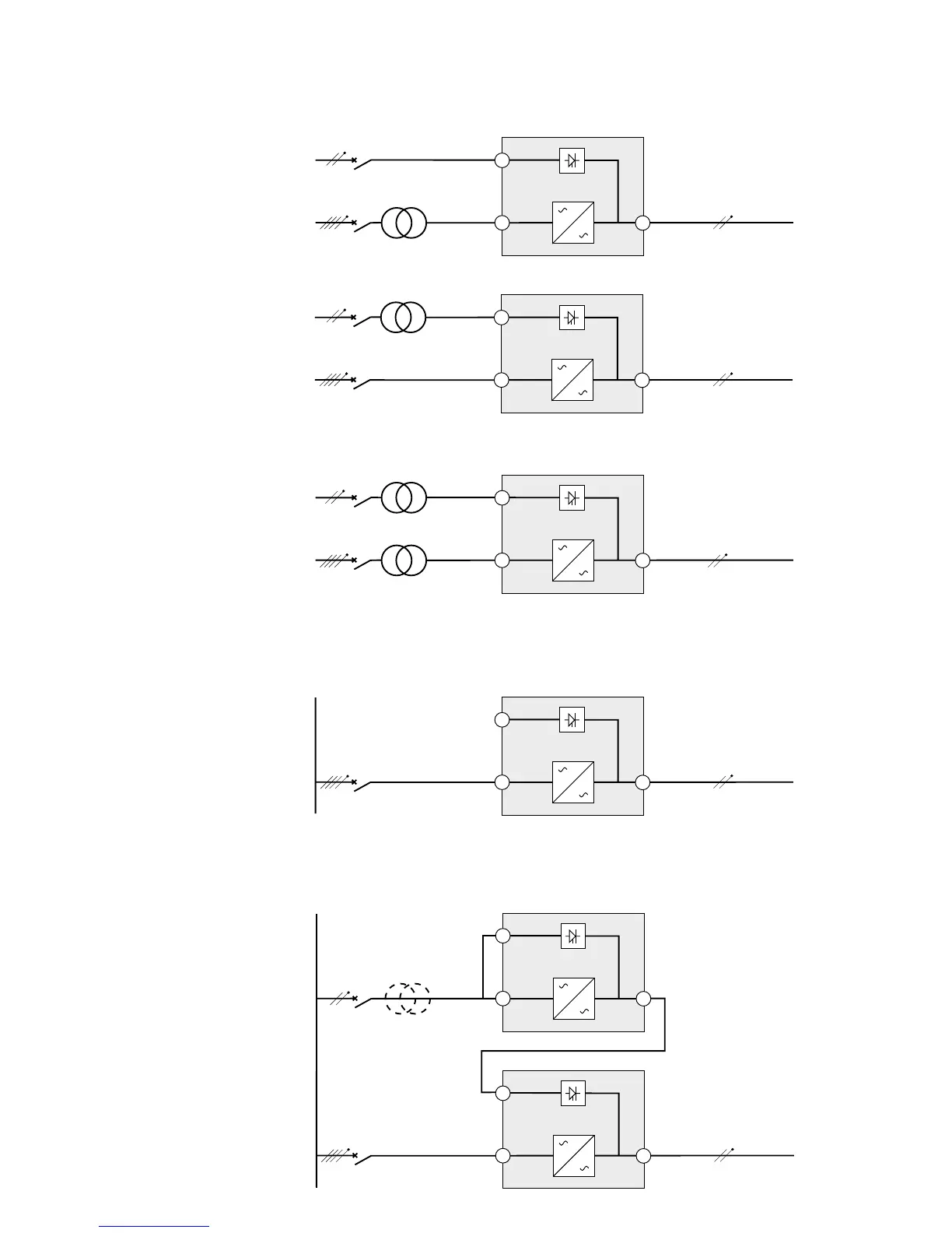
Frequency converter (without Bypass AC input)
Main
low-voltage
switchboard
(MLVS)
Main
low-voltage
switchboard
(MLVS)
2. Installation
UPS with separate Normal and Bypass AC inputs, supplied by separate sources
Change in SEA between upstream and downstream or galvanic isolation required
Hot stand by
Configuration used when the frequency of the application differs from the Mains (Example: marine
requirements).
Configuration used to provide full redundancy (N+1) to critical loads.
(*)
(see page 18)
8
10
11
8
10
11
8
10
11
MLVS 1
MLVS 2
load
load
load
MLVS 1
MLVS 2
or
MLVS 1
MLVS 2
load
load
Bypass AC
Normal AC
Bypass AC
Normal AC
Bypass AC
Bypass AC
Normal AC
Normal AC
Normal AC
Normal AC

Table of Contents

Other manuals for Eaton EX RT 5

Questions and Answers:

Question and Answer IconNeed help?

Do you have a question about the Eaton EX RT 5 and is the answer not in the manual?

Eaton EX RT 5 Specifications

General IconGeneral
BrandEaton
ModelEX RT 5
CategoryUPS
LanguageEnglish

Related product manuals