2. Installation
2.7 Connections of input/output power cables
This type of connection must be carried out by qualified electrical personnel. z
Before carrying out any connection, check that the battery circuit breaker z
12
and that the upstream
protection devices (Normal and Bypass AC sources) are open ("0").
EX RT z UPS always comes from factory with Normal and Bypass AC inputs already connected together,
using a bridge.
Use included insulated ferrules with stranded wires. z
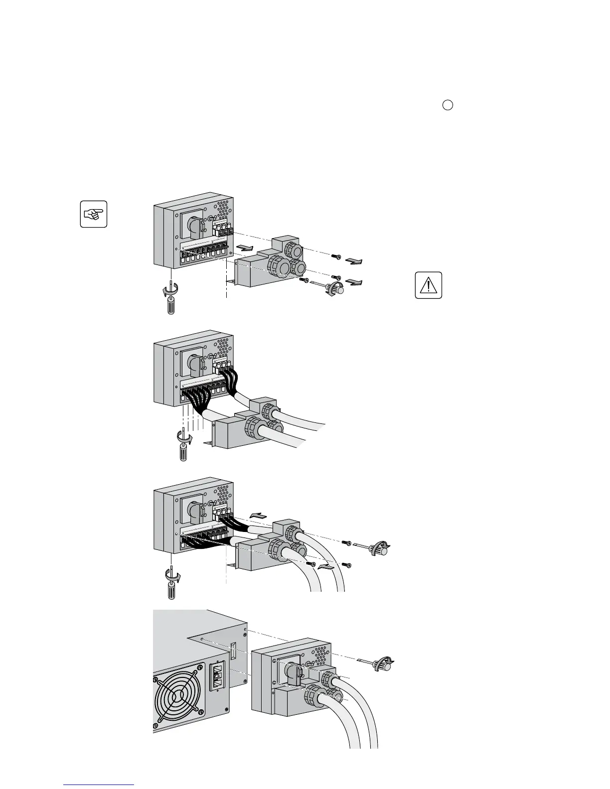
To access the connection terminal
blocks, see section 1.2 "Rear panel":
1 - Remove the terminal block cover
(5 screws),
2 - Insert the Normal AC cable through
the cable gland,
3 - Connect the 5 wires to the Normal
AC terminal block,
Always connect the earthing
wire rst.
4 - Insert the output cable to the load
through the output cable gland,
5 - Connect the 3 wires to the output
terminal block,
6 - Refit the terminal block cover and
tighten the cable glands,
7 - Secure the junction Input/Output
box to the rear of the power module
by means of the 3 screws.
UPS with common Normal and Bypass AC sources
1
4
2
5
3
6
1
6
1
1
6
6
7
1
6
7
7
 Loading...