ELECTRICAL INSTALLATION
Eaton FERRUPS FE/QFE UPS (500 VA–18 kVA) Installation Guide S 164201403 Rev B
www.eaton.com/powerquality
24
Bypass Switches
Bypass switches are available in two types: external (a separate cabinet
that is wall-mounted) or internal (attached to the back of the UPS). The
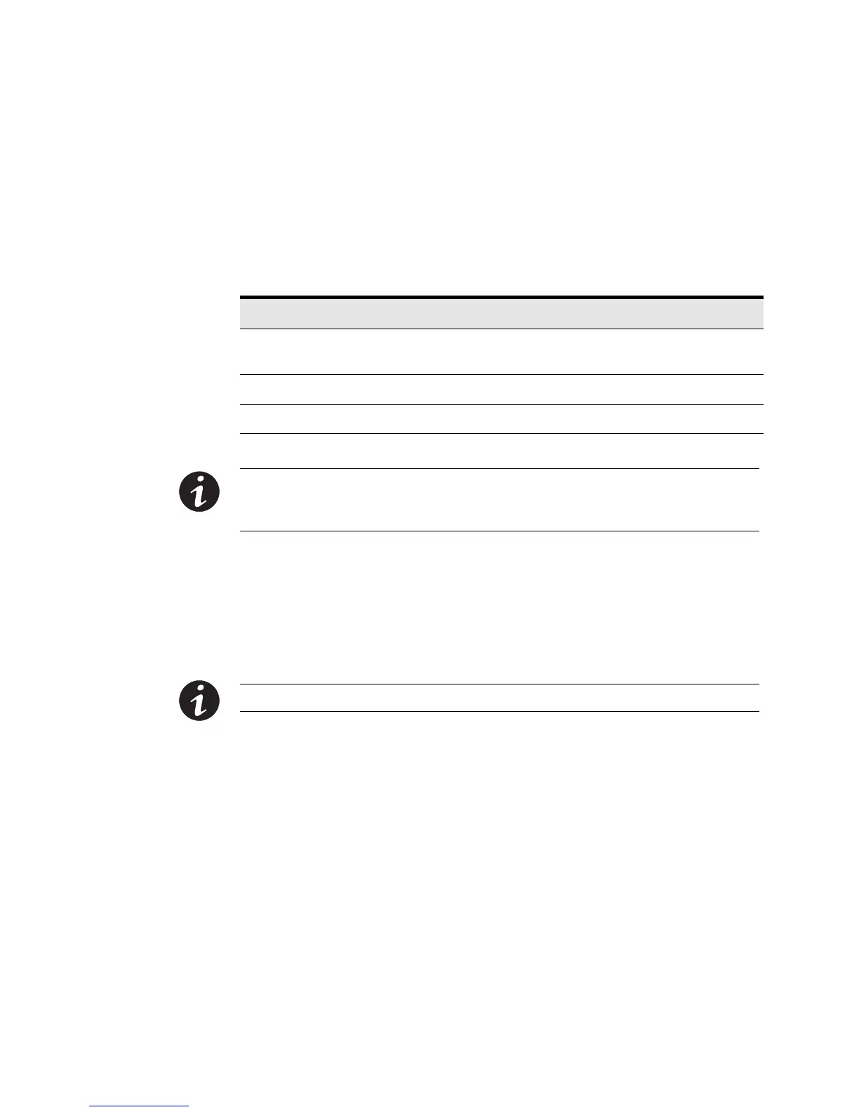
bypass switch has three positions as described in Table 6.
Table 6. Bypass Switch Positions
Switch Position Description
LINE Connects the load directly to AC input power and disconnects UPS
output. AC input power is still connected to the UPS input.
OFF Disconnects the load from the UPS output power and AC input power.
UPS Connects the UPS output to the load.
NOTE In all three positions, AC input power is still connected to the input terminals inside
the UPS (once the UPS is installed). Use the AC disconnect switch (located on the right side
of the bypass switch) to disconnect AC input power during maintenance or service.
Bypass switches may be MBB or BBM.
An MBB switch makes a new connection before it breaks the original
connection. For example, if you turn an MBB switch from UPS to LINE,
the bypass switch connects the load to AC input power before
disconnecting the load from UPS output power.
NOTE MBB switches are not for use with 208 Vac.
A BBM switch breaks the original connection before it makes a new
one. If you turn a BBM switch from UPS to LINE, the switch
disconnects the load from UPS output power before connecting the load
to AC input power.
 Loading...