Matrix Telecom Inverter System
12
Copyright © 2008-2010 Eaton Corporation. All Rights Reserved.
IPN 997-00012-68D February 2010
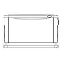
100A STS/controller/interface Chassis
Includes: 23" rack mount brackets (2), interconnection bus bars (3), busbar screws (8),
mounting screws (4), CAN cable for controller (1), DC power cable for controller (1),
communications cable (1), 4-pin jumper (for CN1 if BMS is not used)
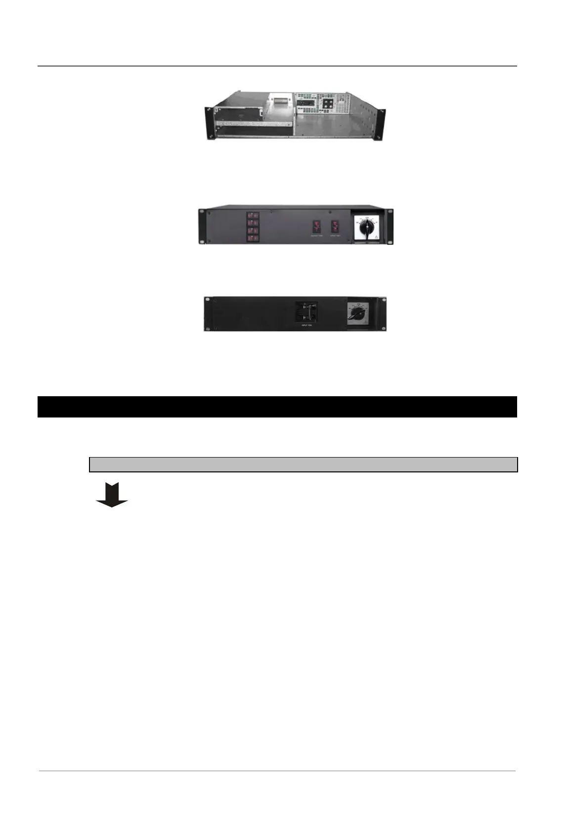
50A MBS/PD Shelf
Includes: 23" rack mount brackets (2), interconnection bus bars (5), busbar screws (5),
mounting screws (4)
100A MBS Shelf
Includes: 23" rack mount brackets (2), interconnection bus bars (5), busbar screws (12),
mounting screws (4), jumper (1), cable grommets (3)
Frame Assembly
Task 1 - Inverter Chassis Assembly
Step 1 - Change mounting brackets if required
The inverter chassis is pre-installed with 19-inch rack brackets.
For 23-inch rack mounting, replace the mounting brackets.
 Loading...