Matrix Telecom Inverter System
28
Copyright © 2008-2010 Eaton Corporation. All Rights Reserved.
IPN 997-00012-68D February 2010
Step 2 - Replace all rear covers
Procedure complete
Module Installation and Removal
Task 10 - Install STS and Inverter Modules
CAUTION: Do not install inverter modules with different specification. This will cause
serious damage, and is not covered by the warranty. Ensure all inverter units have the same
specifications before installation.
Step 1 - Install STS
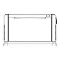
1 If the MBS is fitted then put Maintenance Bypass Switch at MBP or IBP
(Determined by mains and inverter output status) position.
The STS module has a safety lock to prevent insertion/removal if the MBS is
in any other position.
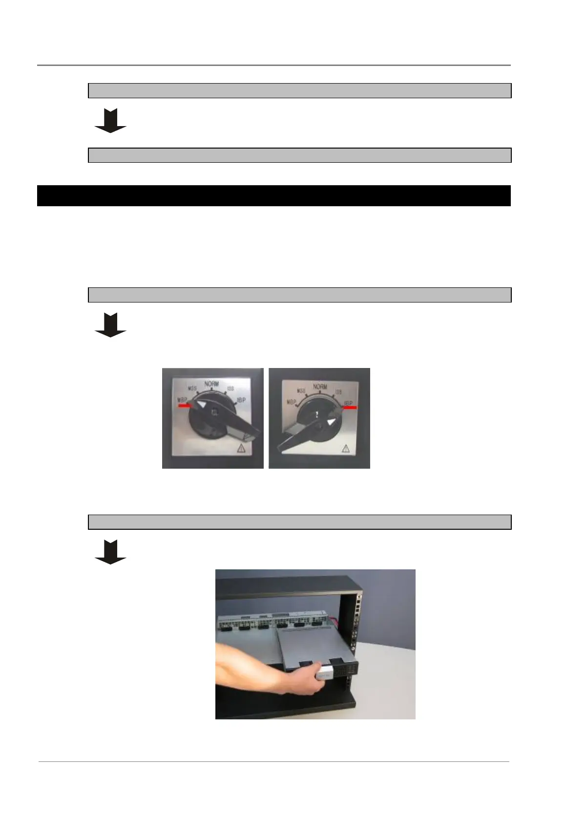
2 Slide the STS into the shelf.
3 Turn the lock bolt counter-clockwise to the LOCK position.
Step 2 - Install inverters
1 Slide in each inverter, two per shelf.
2 Turn the lock bolt counter-clockwise to the LOCK position.
 Loading...