General Description
Copyright © 2008-2010 Eaton Corporation. All Rights Reserved.
IPN 997-00012-68D February 2010
3
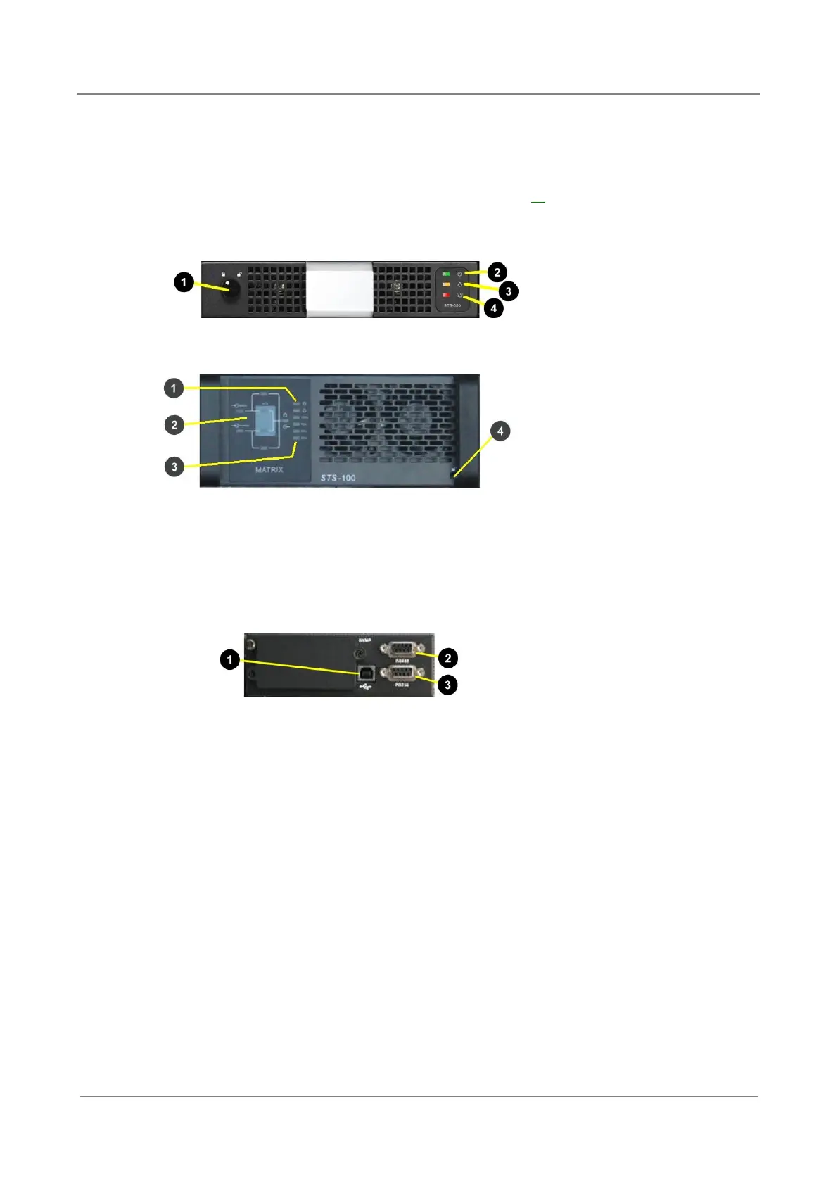
Static Transfer Switch (STS) Module (optional)
The 50A or 100A static transfer switches provide automatic and instantaneous load transfer,
which further secures uninterrupted operation of sensitive electronic equipment.
For more information refer to STS/MBS Operation on page 59
.
50A STS (INV-STS-050)
"
Lock bolt
#
Power on LED (green)
$
Warning LED (yellow)
%
Fault LED (red)
100A STS (INV-STS-100)
"
Alarm LEDs
#
STS operation mode indicator
$
Load indicator LEDs (25%,
50%, 75%, 100%)
%
Lock bolt
Interface Module (optional)
The communication interface module (INV-IFC-1000) allows remote control and monitoring via
USB or RS232 connection.
"
USB port
#
RS485 port (not used)
$
RS232 port
 Loading...