Matrix Telecom Inverter System
30
Copyright © 2008-2010 Eaton Corporation. All Rights Reserved.
IPN 997-00012-68D February 2010
Task 11 - Install Controller and Interface Modules
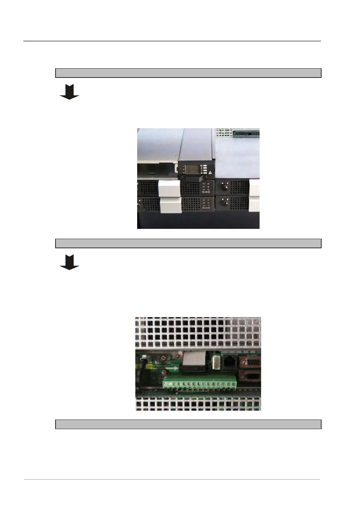
Step 1 - Install the controller module
1 Slide the controller into the 2U-wide controller slot of the pre-wired
controller/interface/STS chassis.
2 Tighten the retaining screws.
With the power on, the green LED of the controller unit would light if
everything functions correctly with the power on.
Step 2 - Install interface module (if required)
1 Remove the interface rear cover.
2 Run the ribbon cable from the interface module CN3 to the interface rear
PCB and connect to CN1.
3 Replace the interface rear cover.
4 Fit the interface module into the 3U-wide interface slot of the pre-wired
controller/interface/STS chassis.
5 Tighten the retaining screw.
Procedure complete
 Loading...