Section 6: Control features
Calendar/clock
Integral to several functions of the control is an internal
real-time calendar/clock. The clock maintains the year,
month, day, hour, minute and seconds, within 1 second. The
display format is user-selectable (see FC 942 and FC 943).
The control time is synchronized to the system frequency
when powered by AC. When ac power is lost, the clock
maintains time for approximately four (4) days, by using
a crystal oscillator and a capacitor as the power source.
Twenty minutes on ac power is required to fully charge the
capacitor.
The LCD displays the current date and time at the end of
the self-test when the front panel is turned on. However,
upon power-up after extended loss of power, the control
clock time and date will default to midnight, January 1,
1970.
The date and time can be read and set at FC 50. When
setting, all of the digits must be entered using the standard
24-hour format (MM/DD/YYYY hh:mm). If an error is made
while entering the values, backspace using the left arrow
key.
Time zone settings are available. ProView NXG software is
required to select a time zone setting; available time zones
are all with respect to Greenwich Mean time. The time zone
setting can be viewed using FC 50 and pressing the down
arrow key once.
Metering
The control has extensive metering capabilities, which
are categorized as Instantaneous, Forward Demand, and
Reverse Demand.
Instantaneous metering
Instantaneous metering values are refreshed once each
second. The information may be accessed using the front
panel HMI under the METERING menu. See Table9 for
a list of available metering values under this menu. See
Table10inSection 5: Control programming for more
information on the function codes.
Demand metering
The control provides forward and reverse demand metering
information for numerous parameters. When applicable,
the present value, high value since last reset and low value
since last reset are recorded. For the low and high values,
the earliest time and date of occurrence are also recorded.
Additionally, the power factor at kVA-high demand and kVA-
low demand are recorded. All demand metering values are
stored in non-volatile memory separately for forward and
reverse power conditions.
Demand metering values may be accessed using the
keypad under the METERING menu; see Table9 for
a list of available metering values under this menu.
SeeTable10inSection 5: Control programming for
information on the function codes associated with demand
metering.
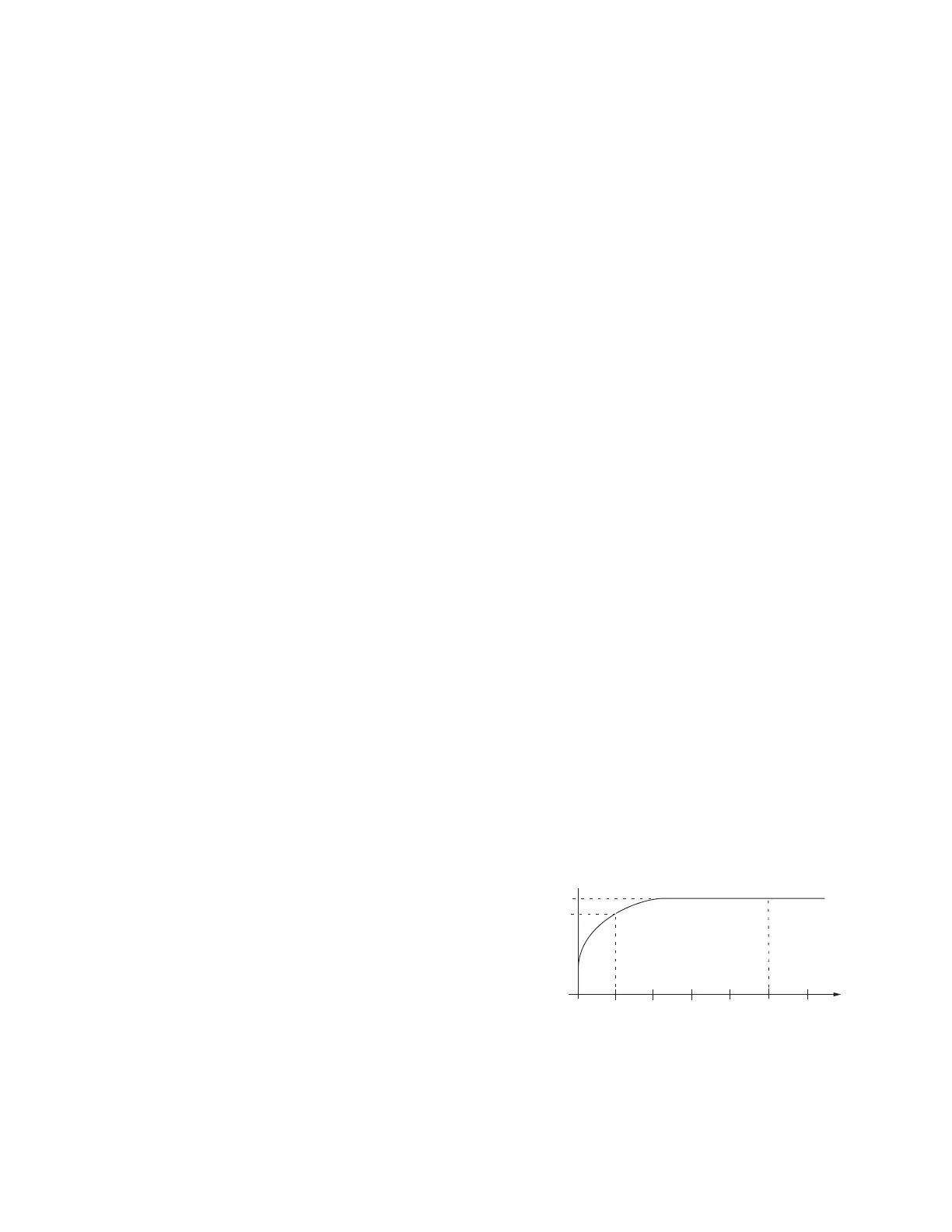
Demand task operation
The demand metering function is based upon a sliding
window concept, or moving integral. The algorithm
implemented simulates the response of a thermal demand
meter which will reach 90% of its final value after one
demand interval in response to a step function input. See
Figure21.
The task works like this:
1. For three (3) minutes after a power outage or power
reversal, no demands are calculated. This allows the
utility system to stabilize from the event which created
the outage or power reversal.
2. At three (3) minutes, the present demands (for
the appropriate power direction) are set to their
corresponding instantaneous value and the integration
algorithm begins according to the programmed demand
interval at FC 46.
3. At fifteen (15) minutes or at the demand time interval
(whichever is longer), the high/low demand values
begin to track the present demand, similar to drag
hands. All demand values are calculated continuously
and, if a change has occurred, the high/low demands
are stored in the non-volatile memory every fifteen
(15) minutes. This prevents loss of data during a power
interruption or outage.
Notice that the provisions are made to reset any demand
value individually using the ENTER key, or all demand
values can be reset simultaneously by entering FC 38. High
and low values will be set to their corresponding present
demand value, and the dates and times will be set to the
present date/time.
Two conditions can cause the present demands to
be invalid: The power has just been applied (within the
3-minute freeze period) or the power flow has changed
direction. If the control is metering in the forward direction,
the reverse present demands will be invalid; if metering in
the reverse direction, the forward present demands will be
invalid.
100%
90%
6T
0
1T
2T
3T
4T
5T
Demand Time Interval
t
Figure21. Demand time interval response
123
INSTALLATION, OPERATION, AND MAINTENANCE INSTRUCTIONS MN225003EN April 2018
CL-7 Voltage Regulator Control
 Loading...