Reverse Co-generation mode
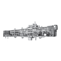
The stand-alone use of the Reverse Co-generation mode is
intended for applications where normal voltage regulation
is occurring in the reverse direction (on the source bushing
side of the voltage regulator), distributed generation is also
present on the source-bushing side of the voltage regulator,
and forward power flow as a result of feeder switching
is not possible. When the control is set for Reverse
Co-generation, a source-bushing voltage, either measured
or calculated, is required. See Figure38.
Figure38. Reverse co-generation regulation points
This mode of operation can also be used in conjunction
with the Bias Co-generation mode as a Bias Co-Gen Alt
Mode. In this use, the control is able to properly respond to
co-generation facilities on both side of a regulator installed
on a loop-configured system where power flow can be
reversed due to feeder switching.
METERING: See Figure39. Always regulates in the reverse
direction except that load center voltage is calculated based
upon the forward line-drop compensation settings (FC 4
and FC 5) when the fixed 1% forward metering threshold
is exceeded. The reverse power indicator turns off when
the forward metering threshold is exceeded. The reverse
line-drop compensation settings (FC 54 and FC 55) are
used when the current exceeds the fixed 1% reverse
metering threshold. The demand values acquired during
forward power flow are stored as forward metered data,
but the values are not scaled (to reflect the other side of
the regulator) since the direction of voltage regulation never
truly reverses to the forward direction.
Figure39. Reverse co-generation metering
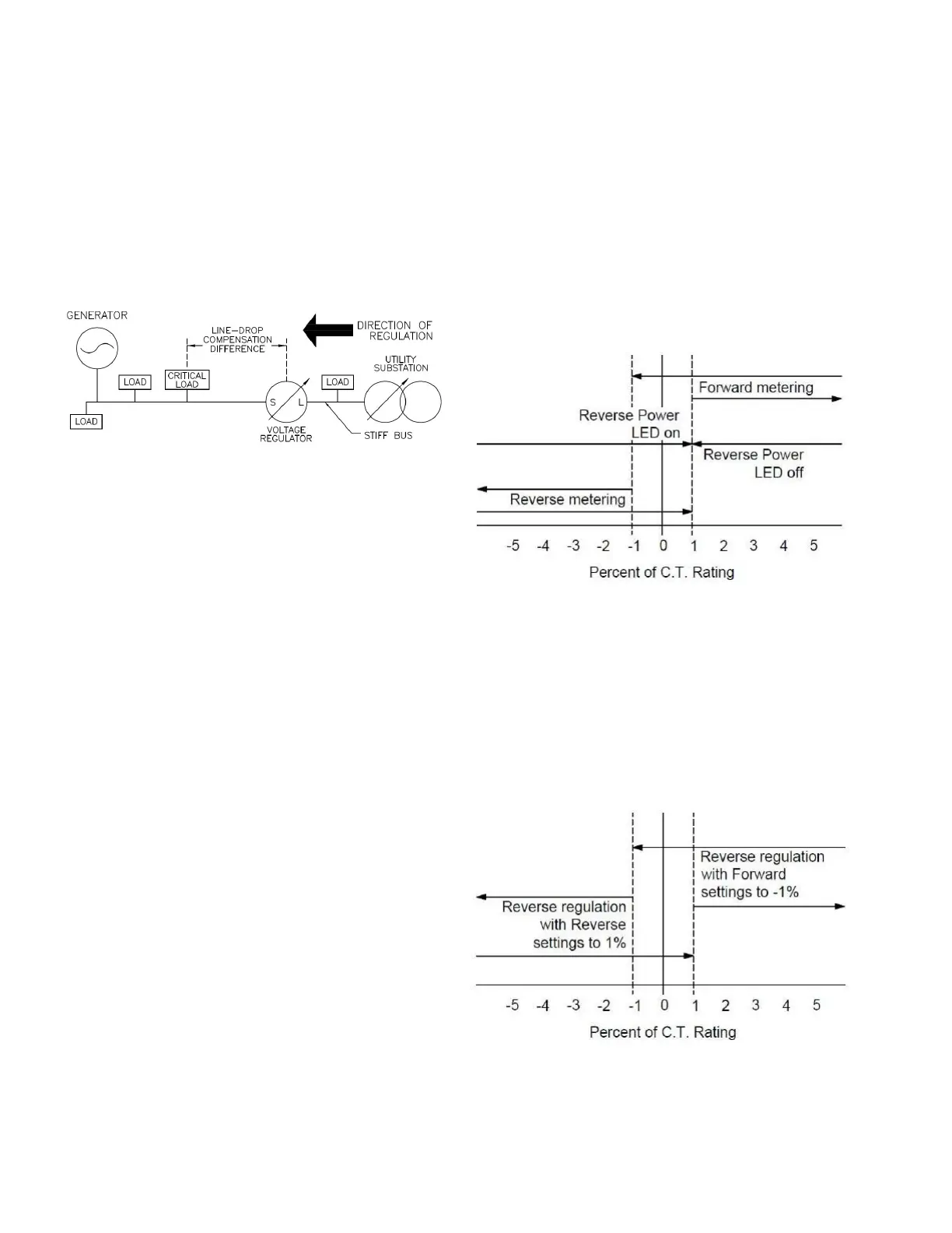
OPERATION: See Figure40. The control always regulates
voltage in the reverse direction. The control will use the
reverse settings for set voltage (FC 52), bandwidth (FC 52),
time delay (FC53) and line-drop compensation (FC 54 and
FC 55) when the real component of the current is beyond
1% fixed reverse metering threshold, but will use the
forward settings (FC 1, FC 2, FC3, FC 4, and FC5) when
the real component of the current is beyond the fixed 1%
forward metering threshold. As the current transitions
between reverse and forward, the settings used will
transition as shown in Figure40.
Figure40. Reverse co-generation operation
134
INSTALLATION, OPERATION, AND MAINTENANCE INSTRUCTIONS MN225003EN April 2018
CL-7 Voltage Regulator Control
 Loading...