INSTALLATION
EATON BladeUPS
®
(12 kVA) User's Guide S 164201649 Rev 4www.eaton.com/powerquality
45
6. Loosely install the Powerware Hot Sync CAN Bridge Card into the open X-Slot
communication bay on the UPS rear panel.
7. Repeat Steps 4 through 6 to install a CAN Bridge Card in each UPS to be
paralleled.
NOTE The BladeUPS parallel system can automatically assign identities to each UPS in the system based
on the order in which their CAN Bridge Cards are wired in Steps 8 through 11. For more information, see
“Auto-Identification” on page 87.
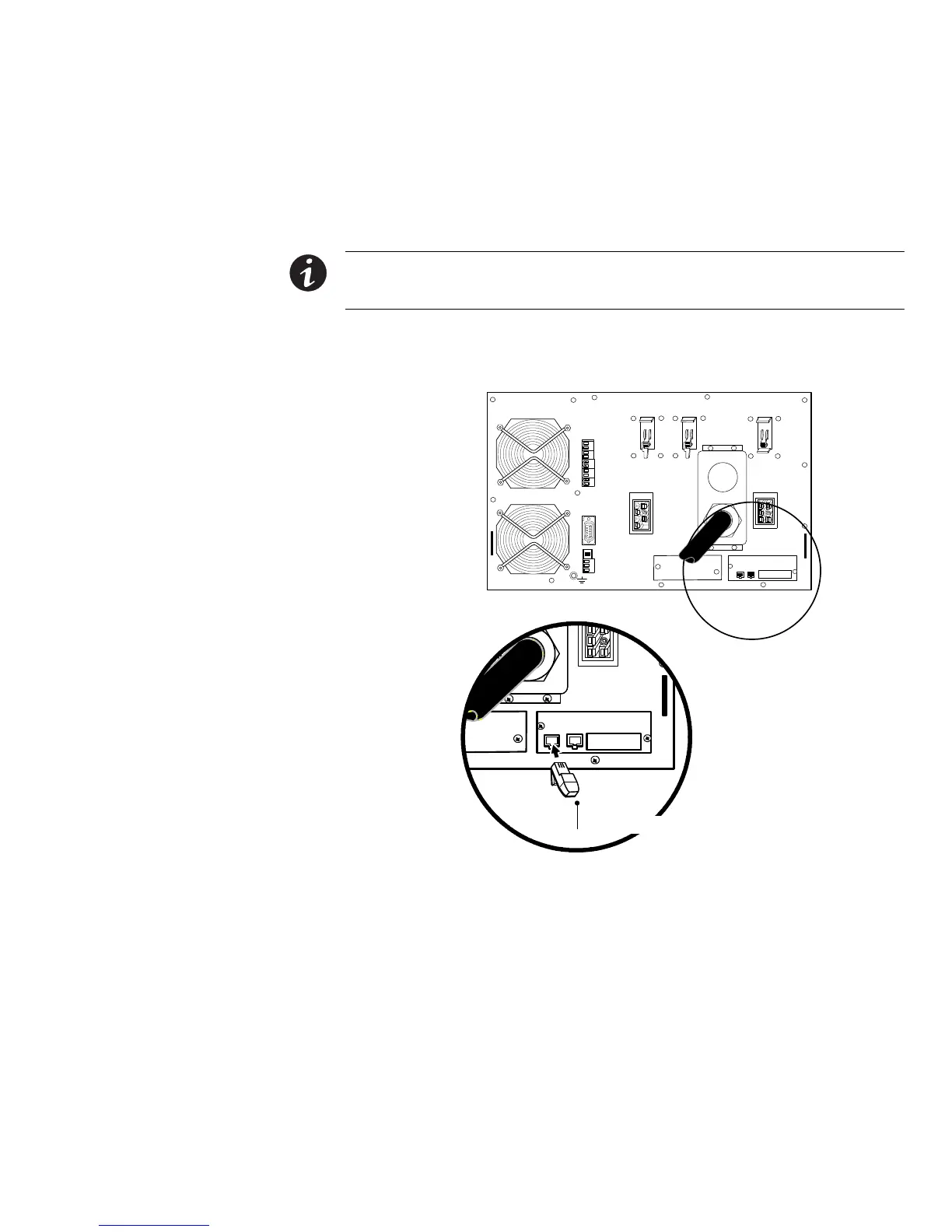
8. Install one of the two supplied blue terminating plugs (see Figure 34) into the
CAN IN port on the first UPS (UPS 1 in Figure 36).
SHIELD
CAN H
CAN L
TX
TX
NO
COM
NC
ALR RTN
ALARM
CAN OU T
CAN IN
Blue Terminating Plug (CAN IN)
Figure 34. Installing the Blue Terminating Plug (First UPS)
 Loading...


