COMMUNICATION
EATON BladeUPS
®
(12 kVA) User's Guide S 164201649 Rev 4www.eaton.com/powerquality
79
Communication Options
The BladeUPS has serial communication capabilities through the DB-9 communication
port or through an X-Slot card in one of the available bays.
The UPS supports two serial communication devices according to the following table:
Table 6. Supported Communication Devices
Independent Multiplexed
X-Slot 1
Communication Bay
X-Slot 2 Communication Bay DB-9 Communication Port
Any X-Slot card Any X-Slot card except the Eaton Modem Card Not in use
Any X-Slot card Eaton Relay Interface Card
Powerware Hot Sync CAN Bridge Card
Available
Any X-Slot card Not in use Available
NOTE You can configure relays, signal inputs, and the serial port baud rate through the front panel menus
(see Table 4 on page 66).
NOTE In a UPS connected to utility power, X-Slot cards remain powered on even if the input breaker is off.
DB-9 Communication Port
To establish communication between the UPS and a computer, connect your
computer to the UPS communication port using the supplied communication cable.
When the communication cable is installed, power management software can
exchange data with the UPS. The software polls the UPS for detailed information on
the status of the power environment. If a power emergency occurs, the software
initiates the saving of all data and an orderly shutdown of the equipment.
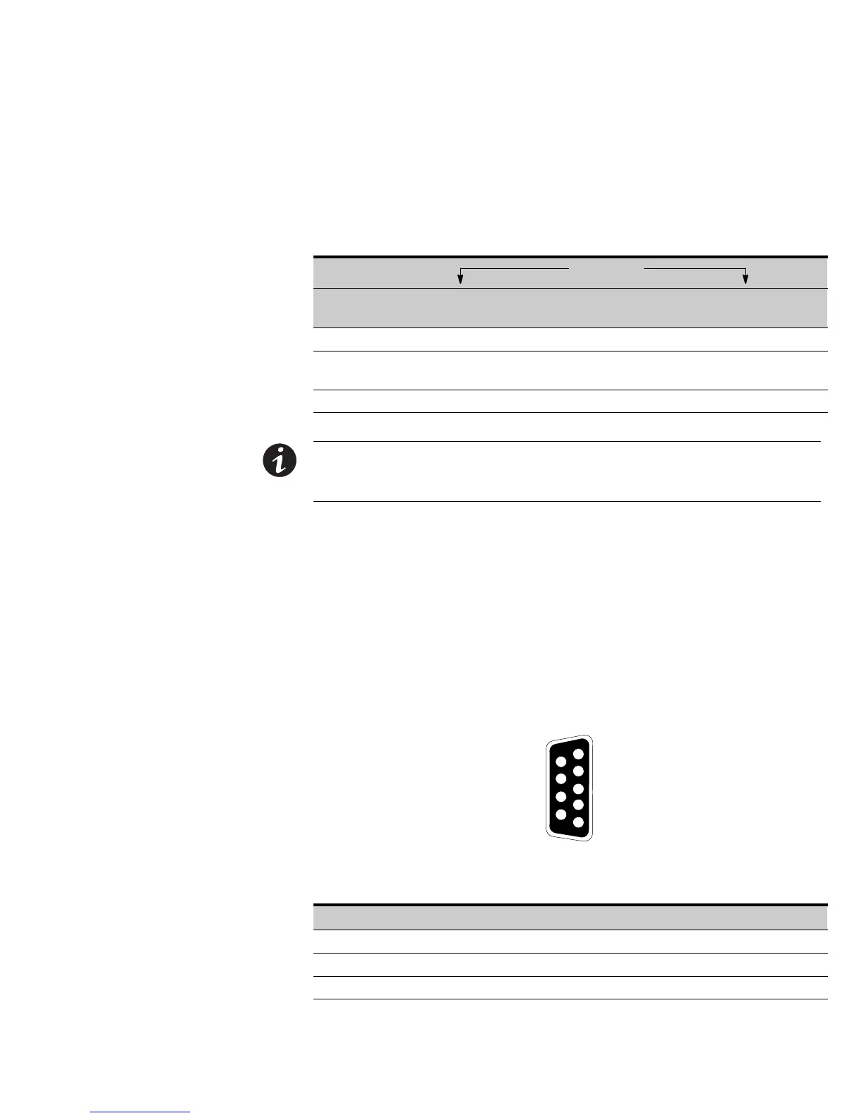
Figure 48 identifies the cable pins and Table 7 describes the pin functions. See
Figure 46 on page 77 for the communication port location.
3
8
7
9
1
6
2
4
5
Figure 48. Communication Port
Table 7. Communication Port Pin Assignment
Pin Number Signal Name Function Direction from the UPS
2 TxD Transmit to external device Out
3 RxD Receive from external device In
5 GND Signal common (tied to chassis) —
 Loading...


