EATON BladeUPS
®
(12 kVA) User's Guide S 164201649 Rev 4www.eaton.com/powerquality
77
Chapter 5 Communication
This chapter describes the:
S DB-9 communication port
S X-Slot cards
S Relay output contacts
S Programmable signal inputs
S Remote emergency power-off (REPO)
S Parallel communication
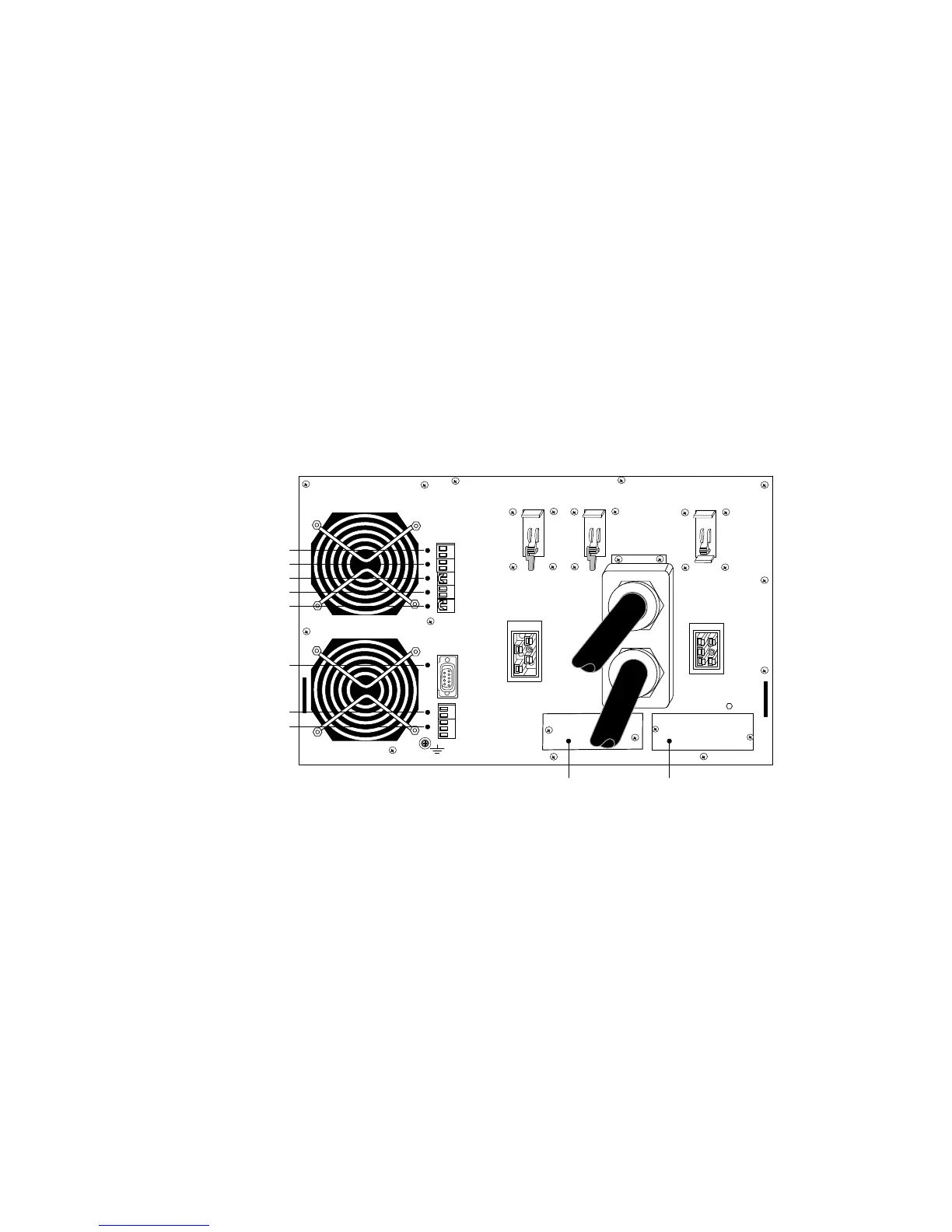
Figure 46 shows the location of the communication options and control terminals on
the UPS.
DB-9 Communication Port
REPO (normally-closed)
REPO (normally-open)
Signal Input 2
Signal Input 1
X-Slot Communication Bay 2X-Slot Communication Bay 1
Relay Output Contacts
Standalone/Parallel
Redundant Signal Wiring
(For Parallel Use Only)
Figure 46. Communication Options and Control Terminals (Standalone UPS shown)
 Loading...


