INSTALLATION
EATON BladeUPS
®
(12 kVA) User's Guide S 164201649 Rev 4www.eaton.com/powerquality
50
3. Verify that all circuit breakers are in the OFF (O) position.
NOTE The load connector breaker controls the load connector only, not the output power cord.
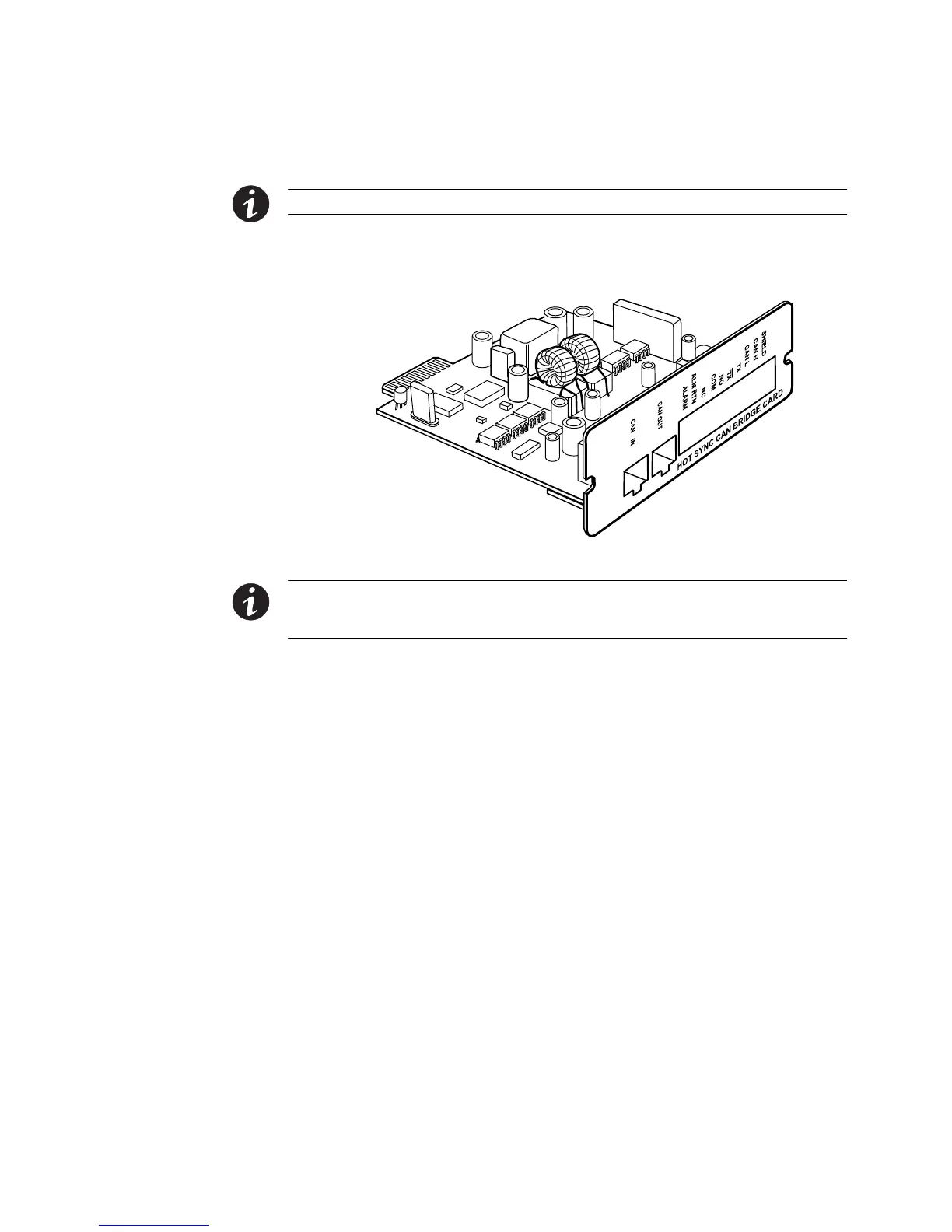
4. Unpack the Powerware Hot Sync CAN Bridge Card and verify that the card was
not damaged during shipment (see Figure 38).
Figure 38. Powerware Hot Sync CAN Bridge Card
NOTE Eaton recommends installing the Powerware Hot Sync CAN Bridge Card in X-Slot Communication
Bay 2 (see Figure 32 on page 43), leaving the X-Slot Communication Bay 1 available for other types of X-Slot
cards.
5. Remove the X-Slot communication bay cover on the UPS and retain the screws.
6. Loosely install the Powerware Hot Sync CAN Bridge Card into the open X-Slot
communication bay on the UPS rear panel.
 Loading...


