Tap-To-Target
Tap To Target is similar to Tap To Neutral except that with
Tap To Target a regulator can be tapped to and held at any
tap position until the feature is deactivated. As with Tap
To Neutral, the feature must first be enabled and then
activated. A third element is also require for Tap To Target
and that is the target tap position.
Enabling Tap To Target can be done by setting FC 171 on the
control to On or by checking a Tap To Target box in ProView
NXG. Tap To Target can be activated using either an analog
input or digital SCADA data point, or using configurable
logic. The third element, target tap position, can be
programmed using FC 172 or entered in the Tap To Neutral
dialog box in ProView NXG.
As a default, there are no analog inputs assigned to activate
the Tap To Target. An analog input can be assigned using
configurable logic in ProView NXG. Assigning one of the
General Purpose Inputs, GPI 1, GPI 2, or GPI 3 would
provide a means to activate the feature by applying either
120 Vac or grounding the terminal board points on the back
panel. The terminal board points are assigned as follows:
GPI 1 is assigned to terminal 5
GPI 2 is assigned to terminal J
GPI 3 is assigned to terminal BR
Making an alternate assignment to a GPI terminal will
deactivate its default fixed functionality.
To activate the feature using digital SCADA, use the data
point Configurable Logic Output From SCADA Tap to
Target Activate.
Remote motor control and auto-tap blocking
Standard, fixed configuration logic programmed into the
control assigns General Purpose Input 3 (GPI 3) to be
the input point for the External Auto Block Active output.
Supplying 120 Vac to the point will inhibit auto-operation
tapping until it is removed. When the motor is controlled
remotely, it is necessary to inhibit automatic operation.
As with the analog input points for voltage reduction, a
whetting voltage from contact point V9 or a 120 Vac whet
contact can be used to activate the auto-tap blocking
feature.
ote:N GPI 3 is assigned to contact point BR as a default.
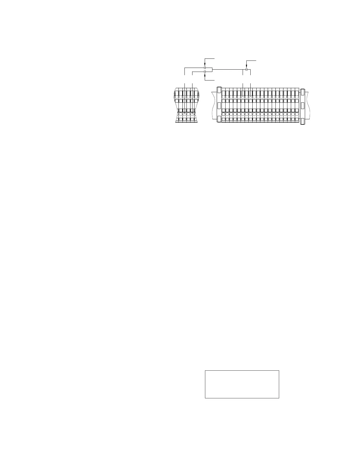
To remotely raise or lower the tap-changer, the appropriate
set of contacts are momentarily closed. Interposing
relays can be used, such that raise and lower contact
closure cannot occur simultaneously. See Figure41 for
recommended connections on a standard back panel with
the TB3 terminal board at the bottom of the control cabinet.
V
9
B
R
L
1
R
1
Control Panel Connection
Raise
Lower
Blocking
Relay
Figure47. Auto-tap blocking and remote motor control
connections shown on the standard back panel with a
TB3 terminal board
Alternate configuration
The CL-7 control panel typically operates with one
set of configuration settings that are programmed or
changed through the keypad or one of the available
communications channels using ProView NXG software.
Alternate Configuration modes allow the CL-7 control to
be programmed with three additional sets of configuration
settings that can then be activated at FC 450. Which
Alternate Configuration is active can be selected at FC 452.
The Alternate Configuration state can be monitored at FC
451 and will display Alt Config 1 Active, Alt Config 2 Active,
Alt Config 3 Active, ARLC Active or ALRH Active.
When an Alternate Configuration mode is activated using
FC 450, a set of alternate configuration settings will become
active and will be used as the basis for the operation of
the control. The control parameters included in the set of
Alternate Configuration settings can be seen in Table9 in
the control menu Features > Alternate Config.
Alternate Configuration settings can be entered using two
methods: 1) Set the individual Alternate Configuration
settings using the control HMI (see Table10 for a list of
applicable function codes). 2) Using ProView NXG software,
enter the Alternate Configuration settings in the Alternate
Configuration Setting dialog box and load the settings using
one of the communications channels.
When the control is in the Alternate Configuration mode,
the display for each of the affected control parameters
will display the statement "(ALT CONFIG X)" at the bottom
where X is the number of the active Alternate Configuration
set. This will indicate that the alternate configuration setting
is active and in use for control operation (see the example
below).
001 Forward
Set Voltage
120.0 Volts
(ALT CONFIG 1)
142
INSTALLATION, OPERATION, AND MAINTENANCE INSTRUCTIONS MN225003EN April 2018
CL-7 Voltage Regulator Control
 Loading...


