P 2500 - P 500
2
All drawings, tables and descriptions in this installation manual refer to the
factory-set (pre-) mounting of the boom holder at the right side.
7.6 Barrier boom
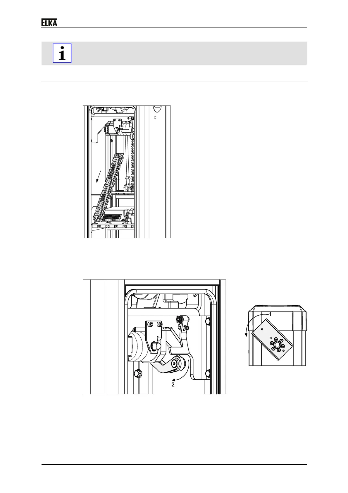
1. Remove all balancing springs from the spring assembly (see below
drawing).
Drawing 13
2. Turn the barrier mechanics (at the boom connector) into position CLOSED
(1). If necessary support the movement by pushing the drive lever in
direction CLOSED (2).
Drawing 14
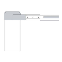
3. Position the barrier boom with the reinforcement plate at the boom
connector. Make sure that the profile of the barrier boom fits tightly
(without play) at the boom connector.
 Loading...