P 2500 - P 500
3
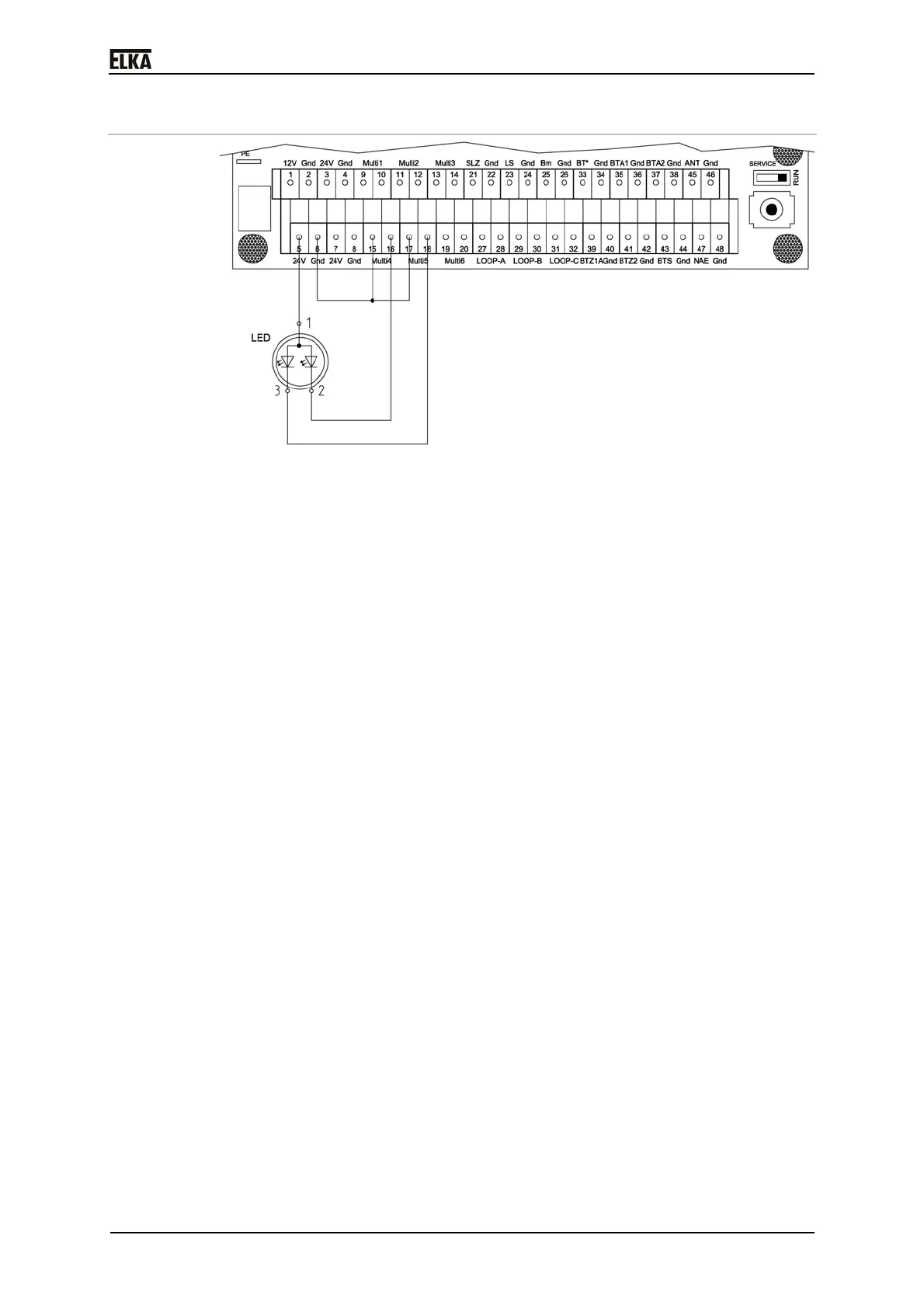
7.9.4 LED boom lighting
Drawing 25
The following instruction explains the connection of the LED boom lighting as
well as the necessary parameter changes in the controller. As an example the
multi-functional relay 4 (MULTI4) and the multi-functional relay 5 (MULTI5) are
being used for the activation as well as the internal 24Vdc power supply of the
controller MO 24 as power supply.
1. Connect the supply line of the LED boom lighting to the terminal row X1,
as shown in the drawing. Use a min. wire cross section of AWG 20.
2. Connect the multi-functional relays 4 and 5 to ground (Gnd) as shown.
3. Activate the multi-functional relay 4 under the sequence point P504 in the
learning sequence of the controller. Select the operating mode “9”. The
multi-functional relay is activated when the barrier is open. During pre-
warning before closing the relay is already deactivated.
4. Activate the multi-functional relay 5 under the sequence point P505 in the
learning sequence of the controller. Select the operating mode “10”. The
multi-functional relay is activated when the barrier is closed. During pre-
warning before opening the relay is already deactivated.
Procedure:
1. The barrier is closed. The LED boom lighting is RED. When an opening
impulse is given, the multi-functional relay 4 is switched off.
2. The barrier opens. The LED boom lighting is off.
3. The barrier is open. The LED boom lighting is GREEN. When a closing
impulse is given, the multi-functional relay 5 is switched off.
 Loading...