18 D6.3.4/0715-0716/E
4.5 Motor protection
Each compressor has a motor protector. An external overload protection is not necessary.
4.5.1 Over-current thermal protection switch for single-phase motors – System A
WARNING
Compressor under voltage! Electrical shock! When the motor stops due
to the over-current thermal protection switch, the compressor is still under
voltage!
This bimetal switch is installed in the terminal box. It is heated by the motor current and by the
motor bundle of laminations, and combines the function of an over-current tripping device and
thermal protection switch. When the switch responds, it interrupts the voltage supply to the motor
directly, not the control line. When the motor winding cools off, it switches on again
automatically.
4.5.2 Thermistor protection – System W
All 3-phase motors with a “W” in the motor code have a thermistor protection device. The
temperature-dependent resistance of the thermistor (also PTC-resistance) is used to sense the
winding temperature. A chain of three thermistors (on 2 and 3 cylinder compressors) or two
chains of three thermistors each (on 4, 6 and 8 cylinder compressors) connected in series are
embedded in the motor windings in such a manner that the temperature of the thermistors can
follow with little inertia.
An electronic release module is required which switches a control relay, depending on the
thermistor resistance. The release module INT69-2 for one thermistor chain or two chains with a
5-minute time delay, INT69TM-2 for two chains, is installed in the terminal box to which the
thermistors are connected.
Caution: The maximum test voltage for thermistors is 3V.
The total resistance of the thermistor chains on a cold compressor should be ≤ 1800Ω.
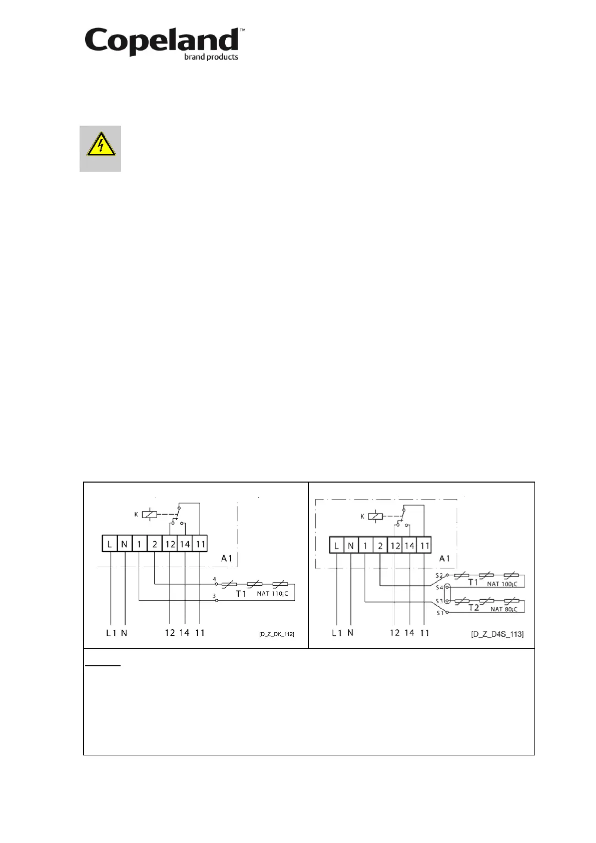
Internal wiring: The current compressors use a new generation of thermistor protection
(INT69-2 & INT69TM-2) that has the same main features as the previous one (INT69 &
INT69TM).
INT69-2 (K, L, D2, D3, 2D, 3D) INT69TM-2 (D4, D6, D8, 8D)
Legend
L ...... Voltage connection 3+4 ........ Cable bushings of thermistor connections
N ...... Neutral connection in terminal box (K, L, 2S not marked)
1+2 ... Thermistor chain connection S1-S4 .... Cable bushings of thermistor connections
12 ..... Alarm connection in terminal box (4, 6 & 8 cyl.)
14 ..... Control circuit T1+T2 ... Thermistor chain (about 90Ω to 750Ω per
11 ..... Control voltage connection chain at +20°C)
A1 .... Release module NAT....... Nominal response temperature
Figure 15
Protection class IP20.
 Loading...


