D6.3.4/0715-0716/E 19
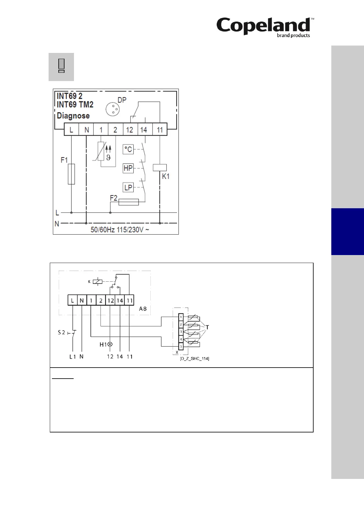
Control circuit wiring:
IMPORTANT
Different sources for power supply and contact 11-14! Module
malfunction! Use the same potential for the power supply and the switch
contact of the control loop (11-14).
Figure 16
4.6 Discharge temperature protection
Legend
L ........ Voltage connection H1 ...... Signal lamp “fault”
N ........ Neutral connection T ........ PTC sensor (resistance of one thermistor
1+2 ..... Sensor connection at 20°C is between 30Ω & 250Ω; measuring
12 ....... Alarm connection voltage 3V maximum)
14 ....... Control circuit X ........ Additional terminal box
11 ....... Control voltage connection A8 ...... Release module for discharge temperature
S2 ...... Reset button protection
Figure 17
Protection class IP55.
 Loading...


