10
© 2015 Emerson Climate Technologies, Inc. All rights reserved.
AE4-1395 R5
remove latent heat. In desert and arid climates, because
oflowornolatentloads,airowislesscritical.
Thecontrolsrequiredforvariableairowarenotprovided
by Emerson so the contractor may need to consult with
controlsexpertsinthiseld.
Condenser Air Flow
Modulatingthe condenserairowisnotcriticaltothe
success of the application. For the highest level of energy
savings,condenserairowwillbereducedbasedonthe
compressor modulation rate, condensing temperature,
ambient temperature, etc.
Modulation Control
Thepreferredmodulationcontrolforretrotapplications
is the Commercial Comfort Controller. This controller is a
closed loop controller that is installed in the conditioned
space. The controller measures the space temperature
and through an algorithm in the controller, controls the
modulation of the digital scroll. The controller can be
positioned up to 300 feet from the compressor/unit, is
congurableforrooftopunitorheatpump,andiswired
like a commercial room thermostat. For more information
on the Commercial Comfort Controller please refer to
AE8-1393.
ASSEMBLY LINE PROCEDURES
Modulation Valve Brazing Procedure
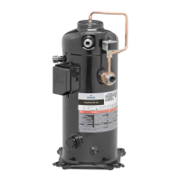
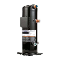
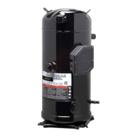
ZPD34-ZPD54K5, ZPD61-ZPD83KC, ZPD91KC,
ZPD104KCE, ZPD122KCE, and ZRD36-81KC
The external modulation valve is purchased and
shipped separately from the ZPD34-ZPD54K5, ZPD61-
ZPD83KC, ZPD91KC, ZPD104KCE, ZPD122KCE,
and ZRD36-81KC digital scroll. Therefore, assembly
is required in the OEM manufacturing plant. Figure
6 illustrates the correct position and orientation of the
modulation valve. Please note the direction of the arrow
on the valve, it must point to suction.
When brazing the modulation valve into the system,
the valve must be wrapped with a wet rag to help keep
thevalvecool.Thetorchamemustbedirectedaway
from the valve and the brazing operation should be
done quickly so the valve isn't overheated. The brazing
operation should be performed with a nitrogen purge to
prevent the build-up of copper oxide. The solenoid coil
should be installed after the brazing operation, so the
leads are kept away from the brazing operation and the
wet rag is able to fully contact the valve body.
Pressure Testing
The pressure used on the OEM assembly line to meet
the UL burst pressure requirement cannot be higher
than 400 psig (27.6 bar) for R-407C & R-22 and 475
psig (32.8 bar) for R-410A. Higher pressure may result
in permanent deformation of the compressor shell and
possibly cause misalignment or bottom cover distortion.
SERVICE PROCEDURES
Modulation Troubleshooting
The modulation valve and solenoid coil are engineered
forspecic usewiththe digitalscroll.Don’tattemptto
substitute replacement solenoid coils that are not of the
correct part number. The ZPD34-ZPD54K5, ZPD61-
ZPD83KC, ZPD91KC, ZPD104KCE, ZPD122KCE, and
ZRD36-81KC modulation valves must be installed in
the correct orientation and with the arrow on the valve
pointing to suction. Installing a modulation valve in a
horizontal position, or with the suction and discharge
connections reversed, can result in sporadic operation
of the modulation valve. See Figure 6 for an illustration
of the correct valve location and orientation.
Figure 8 is a troubleshooting ow chart to help with
simple modulation problems. For more information on
troubleshooting the Copeland
™
Digital Compressor
Controller please refer to AE8-1328. For more
information on troubleshooting the Emerson Commercial
Comfort Controller please refer to AE8-1393.
Modulation Valve Replacement Procedure
ZPD34-ZPD54K5, ZPD61-ZPD83KC, ZPD91KC,
ZPD104KCE, ZPD122KCE, and ZRD36-81KC
The ZPD34-ZPD54K5, ZPD61-ZPD83KC, ZPD91KC,
ZPD104KCE, ZPD122KCE, and ZRD36-81KC digital
scroll compressors employ a modulation valve that is
mounted external to the compressor in the modulation
tubing. To replace the modulation valve, follow these
recommended steps:
1. Disconnect and lockout the power to the unit.
2. Recover the refrigerant charge from the compressor/
system.
3. Remove the screw holding the coil to the valve
using a Phillips screwdriver or appropriate size nut
driver.
4. Remove the coil from the valve.
5. Using manifold gauges, double check to make
sure the refrigerant charge is completely
 Loading...
