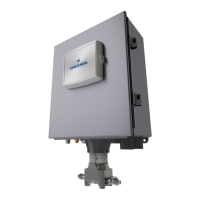
Emerson FB2200 Flow Computer Instruction Manual
D301784X012
March 2019
6 Introduction
Base I/O consists of:
▪
Pressure (P) input from the MV sensor, differential pressure (DP) input from the MV sensor,
connections for temperature (T) input from a customer-supplied RTD/PRT -or – a single
Static Pressure Sensor with RTD/PRT connections. Alternatively, you can purchase the flow
computer without an integral sensor.
▪
Two on-board I/O channels that you can individually configure as digital input (DI), digital
output (DO), or pulse input (PI)
▪
Two on-board I/O channels that you can individually configure as either analog input (AI) or
analog output (AO)
An optional 8-channel expansion I/O board includes:
▪
Four I/O channels that you can individually configure as digital inputs (DI), digital outputs
(DO), or pulse inputs (PI)
▪
Four I/O channels that you can individually configure as either analog inputs (AI) or analog
outputs (AO)
If the optional 8-channel expansion I/O board is present, the device can optionally support an
additional 6-channel expansion I/O board which includes:
▪
Four I/O channels that you can individually configure as digital inputs (DI), digital outputs
(DO), or pulse inputs (PI)
▪
Two I/O channels that you can individually configure as either analog inputs (AI) or analog
outputs (AO)
Table 1-2. FB2200 I/O Configurations
▪
MV Sensor (P, DP) or Static
Pressure (SP) Sensor
▪
Connections for customer-
supplied 2-, 3-, or 4-wire
RTD/PRT
10 DI/DO/PI channels (4 residing
on the 8-channel expansion I/O
module and 4 residing on the 6-
channel expansion I/O module)
8 DI/DO channels (4 residing on
the 8-channel expansion I/O
module and 2 residing on the 6-
channel expansion I/O module)

 Loading...


