EasyManua.ls Logo

Emerson FB2200 User Manual

Emerson FB2200
124 pages
To Next Page IconTo Next Page
To Previous Page IconTo Previous Page
Page #84 background imageLoading...
Page #84 background image
Emerson FB2200 Flow Computer Instruction Manual
D301784X012
March 2019
80 I/O Configuration and Wiring
3.8 Wiring a Digital Output to the Optional Relay
The flow computer supports two optional electro-mechanical relays for switching on/off external
circuits or devices. If you order this option, the relays ship from the factory mounted to the top of
the battery compartment inside the flow computer enclosure.
You can wire a relay to an isolated DO (Figure 3-17). You must also use the isolated GND and
provide 24V to power the relay. To attach a wire, insert it into the connector and tighten the
adjacent screw to secure it. The NO and COM wires go to the external circuit or device.
Figure 3-17. Relay Wired to Isolated DO
1
To customer load
Alternatively, you can wire a relay to a non-isolated DO (Figure 3-18). In that case, you must use the
non-isolated GND and provide 24V to power the relay. To attach a wire, insert it into the connector
and tighten the adjacent screw to secure it. The NO and COM wires go to your external circuit or
device.

Table of Contents

Other manuals for Emerson FB2200

Question and Answer IconNeed help?

Do you have a question about the Emerson FB2200 and is the answer not in the manual?

Emerson FB2200 Specifications

General IconGeneral
BrandEmerson
ModelFB2200
CategoryDesktop
LanguageEnglish

Summary

Device Safety Considerations

Reading these Instructions

Understand safety implications before operating the device; keep manual handy.

Protecting Operating Processes

Consider backup equipment to protect processes from device failure.

Returning Equipment

Ensure equipment is cleaned to safe levels before returning it.

Grounding Equipment

Ground metal enclosures and exposed metal parts per OSHA and NEC.

Protecting from Electrostatic Discharge (ESD)

Handle ESD-sensitive components carefully to prevent damage.

System Training

Section 1: Introduction

Safety Labels

Identifies potential hazards using specific labels; consult documentation for details.

Features

Lists key features of the FB2200 flow computer.

FB2200 Flow Computer Models

Describes the two basic models and enclosure options.

Central Processing Unit (CPU)

Details the CPU type and processor.

Memory

Describes the static and flash memory types and capacities.

Inputs & Outputs (I/O)

Lists base I/O and optional expansion modules.

Power Options

Details options for powering the device.

Communications

Describes available communication ports and protocols.

Human-Machine Interface (HMI) Module

Explains the HMI module's display and LEDs.

FBxWifi™ Communications

Details wireless communication capabilities.

Software Tools

Introduces the FBxConnect configuration software.

RoHS2 Compliance

States compliance with RoHS2 EU Directive.

Physical Security

Discusses methods for securing the enclosure.

Section 2: Installation

Hazardous Locations

Certifications for Class I Division 2 and ATEX Zone 2.

Environmental Specifications

Summarizes environmental parameters for the device.

Required Tools

Lists tools needed for installation and servicing.

Site Considerations

Factors to consider for installation location.

General Wiring Guidelines

Best practices for wiring connections.

Grounding

Instructions for properly grounding the unit.

Opening/Closing the Enclosure

Procedures for opening and closing the enclosure.

Mounting the Enclosure

Methods for mounting the flow computer.

Bolting Considerations

Guidelines for bolting flange assemblies.

O-rings with Flange Adapters

Proper use and inspection of O-rings.

Pole Mounting – Aluminum Enclosure

Instructions for pole mounting aluminum enclosures.

Pole Mounting – Fiberglass Enclosure

Instructions for pole mounting fiberglass enclosures.

Panel/Wall Mounting Dimensions – Aluminum Enclosure

Dimensions for mounting aluminum enclosures on panels/walls.

Panel/Wall Mounting Dimensions – Fiberglass Enclosure

Dimensions for mounting fiberglass enclosures on panels/walls.

Rotating the Housing

How to rotate the housing for accessibility.

Power Modes

Explains Low Power and Standard Power modes.

Connecting Power

Instructions for connecting DC and battery/solar power.

Installing the Optional 30W Solar Panel

Steps for installing the solar panel kit.

Adjusting the Optional Solar Panel

How to set the solar panel tilt angle.

Connecting Communication Ports

Guidance for connecting communication cables.

Door Contact Terminal

Information on the door contact terminal.

Section 3: I/O Configuration and Wiring

Analog Inputs

Details the available analog input channels and configurations.

Analog Outputs

Details the available analog output channels and configurations.

Digital Inputs

Details the available digital input channels and configurations.

Digital Outputs

Details the available digital output channels and configurations.

Pulse Inputs

Details the available pulse input channels and configurations.

Connecting the RTD/PRT

Instructions for connecting RTD/PRT sensors.

Wiring a Digital Output to the Optional Relay

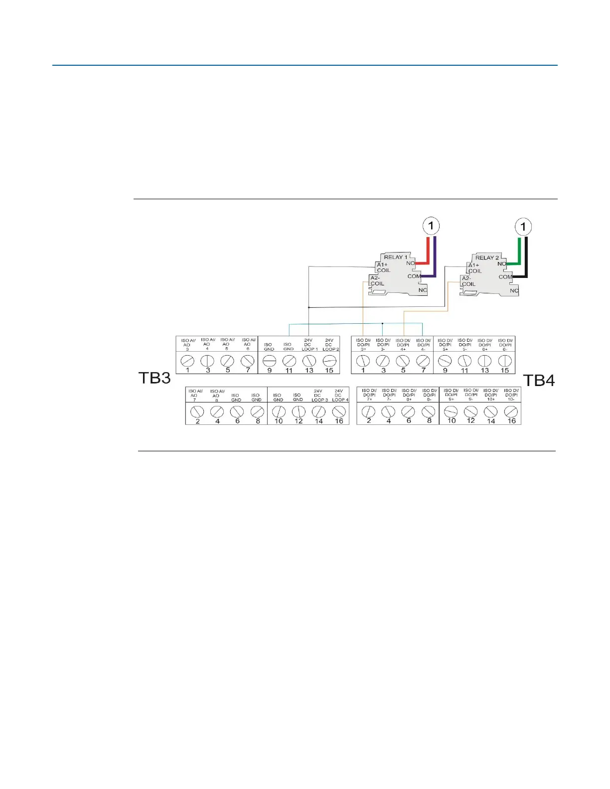
Wiring digital outputs to relays.

Radio Wiring

Instructions for wiring radio components.

Section 4: Operation

Powering Up/Powering Down the Device

Procedures for turning the device on and off.

Establishing Communications

Methods for establishing communication with the device.

Communicating using the HMI Module

How to communicate using the HMI module.

Section 5: Service and Troubleshooting

Returning the Unit for Repairs

Procedure for returning the unit for service.

Interpreting the Status LEDs

Explains the meaning of the status LEDs.

Switch and Buttons

Describes the function of switches and buttons for troubleshooting.

Removing/Replacing the HMI Module

Steps for removing and replacing the HMI module.

Replacing the Main Battery Pack

Procedure for replacing the main battery.

Removing/Replacing the SRAM Battery

Steps for replacing the SRAM backup battery.

Upgrading System Firmware

How to update the system firmware.

Appendix A: Special Instructions for Class I Division 2 Locations

Class I Division 2

Requirements for Class I Division 2 hazardous locations.

Appendix B: ATEX Non-Sparking Zone 2 Certifications

ATEX Zone 2

Notes on ATEX certifications for Zone 2.

Related product manuals