Maintenance and Troubleshooting
September 2013
7-15
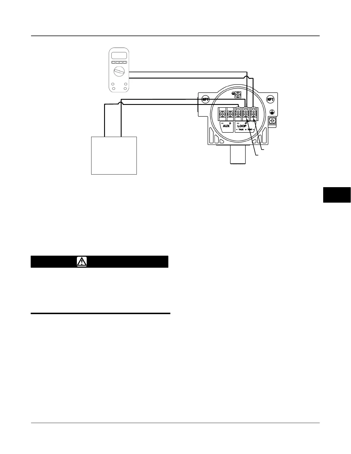
LOOP + / TEST +
TEST −
DCS SYSTEM (OR OTHER
CURRENT SOURCE)
4−20mA
CURRENT
SOURCE
+
−
LOOP −
LOOP + / TEST +
LOOP + / TEST +
TEST −
NOTES:
1. MULTIMETER MEASURING 0.000 TO 1.0000 VDC
2. TYPICAL READINGS 0.004 VDC TO 0.020 VDC
3. OHM’S LAW—V = I x R, WHERE R = PRECISION 1 OHM RESISTOR, V = I x 1, SO V= I
MULTIMETER
(SEE NOTES
BELOW)
0.020
DVC6000 DIGITAL VALVE
CONTROLLER TERMINAL BOX
Figure 7-8. Check the Loop Current using the TEST Terminals
Checking the Loop Current Without
Disturbing the Loop Wiring
WARNING
Personal injury or property damage
caused by fire or explosion may occur
if this test is attempted in an area
which contains a potentially explosive
atmosphere or has been classified as
hazardous.
To check the loop current without disturbing the loop
wiring perform the following procedure.
1. With the FIELDVUE instrument connected to a
current source connect a digital multimeter reading
Volts DC ( 0 to 1 VDC or mV scale) to the TEST
terminals as shown in figure 7-8.
2. The reading at the test terminals is proportional to
the loop current [0.004 V = 0.004 A (4 MA)] mA of
loop current). Refer to Specifications, table 1-2, to
determine if the current is sufficient.
7

 Loading...


