Quick Start Guide
D103556X012
DVC6200 Digital Valve Controllers
July 2017
26
HART Devices
Refer to the DVC6200 HW1, DVC6200 HW2, or DVC6200 SIS instruction manual, available at Fisher.com or from your
Emerson sales office or Local Business partner, for additional information.
The digital valve controller is normally powered by a control system output channel. Shielded cable will ensure proper
operation in electrically noisy environments.
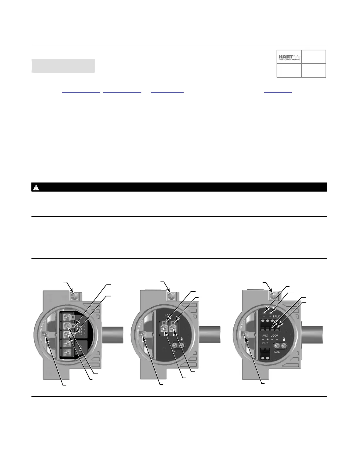
Wire the digital valve controller as follows, refer to figure 21:
1. Remove the wiring terminal box cap.
2. Bring the field wiring into the terminal box. When applicable, install conduit using local and national electrical codes
which apply to the application.
3. Connect the control system output channel positive wire to the LOOP + screw terminal in the terminal box. Connect
the control system output channel negative (or return) wire to the LOOP - screw terminal in the terminal box.
WARNING
Personal injury or property damage, caused by fire or explosion, can result from the discharge of static electricity. Connect
a 14 AWG (2.08 mm
2
) ground strap between the digital valve controller and earth ground when flammable or hazardous
gases are present. Refer to national and local codes and standards for grounding requirements.
4. As shown in figure 21, two ground terminals are available for connecting a safety ground, earth ground, or drain
wire. The safety ground is electrically identical to the earth ground. Make connections to these terminals following
national and local codes and plant standards.
Figure 21. Loop and Talk Connections
TALK +
TALK -
LOOP -
LOOP +
SAFETY GROUND
SAFETY GROUND
LOOP +
LOOP -
EARTH
GROUND
TALK +
TALK -
EARTH
GROUND
TALK -
TALK +
SAFETY GROUND
LOOP +
LOOP -
EARTH
GROUND
X0430
X0431
X0439
SIS

 Loading...


