Quick Start Guide
D103556X012
DVC6200 Digital Valve Controllers
July 2017
33
Step 4—Configure the Digital Valve Controller
WARNING
D Select wiring and/or cable glands that are rated for the environment of use (such as hazardous area, ingress protection
and temperature). Failure to use properly rated wiring and/or cable glands can result in personal injury or property
damage from fire or explosion.
D Wiring connections must be in accordance with local, regional, and national codes for any given hazardous area
approval. Failure to follow the local, regional, and national codes could result in personal injury or property damage
from fire or explosion.
D To avoid personal injury resulting from electrical shock, do not exceed maximum input voltage specified on the product
nameplate. If the input voltage specified differs, do not exceed the lowest specified maximum input voltage.
D Personal injury or property damage caused by fire or explosion may occur if electrical connections are attempted in a
potentially explosive atmosphere or in an area that has been classified as hazardous. Confirm that area classification
and atmosphere conditions permit the safe removal of the terminal box cover before proceeding.
D The valve may move in an unexpected direction when power is applied to the digital valve controller. To avoid personal
injury and property damage caused by moving parts, keep hands, tools, and other objects away from the
valve/actuator assembly when applying power to the instrument.
D While configuring the digital valve controller the valve may move, causing process fluid or pressure to be released. To
avoid personal injury and property damage caused by the release of process fluid or pressure, isolate the valve from the
process and equalize pressure on both sides of the valve or bleed off the process fluid.
D Changes to the instrument setup may cause changes in the output pressure or valve travel. Depending on the
application, these changes may upset process control, which may result in personal injury or property damage.
CAUTION
Before proceeding, check that all pressure connections, fasteners, and plugs are installed and tightened.
For remote mount installations, ensure that the Base Unit is wired to the Feedback Unit before providing electrical power.
Failure to do so may cause the DVC6205 to go into “Pressure Control” mode if Pressure Fallback is configured. The unit can
be returned to “Travel Control” mode using Detailed Configuration.
1. Install the latest version of the communication software on the user interface tool. This may include Device
Descriptions (DD, EDD), ValveLink
™
software, Device Type Manager (DTM), or GSD. Refer to table 1 below.
Contact your local Emerson sales office
or Local Business Partner to ensure that you have the latest software version
or for information on locating the necessary files.
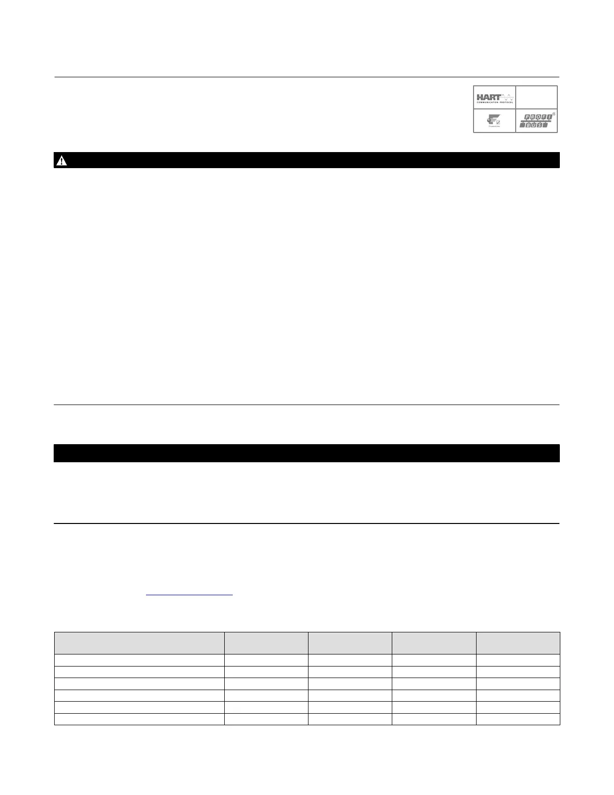
Table 1. User Interface Tools and Software Available for Instrument Configuration and Calibration
DVC6200
HART
DVC6200 SIS
HART
DVC6200f
F
OUNDATION fieldbus
DVC6200p
PROFIBUS PA
475 Field Communicator (DD) Ļ Ļ Ļ
AMS Device Manager (DD) Ļ Ļ Ļ
ValveLink Software Ļ Ļ Ļ
ValveLink Mobile Software Ļ Ļ Ļ
Field Device Type Frame (DTM) Ļ Ļ Ļ
Siemens SIMATIC
™
PDM Software (DD, GSD) Ļ
SIS

 Loading...


