Instruction Manual
D104239X012
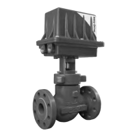
Multiport Flow Selector
January 2019
6
down by tightening the nuts. Proper assembly has occurred if there are flat washers between the travel indicator
spacers and travel indicator plate and travel indicator plate and nuts.
Regardless of size, an anti-seize lubricant (key 40) shall be applied to the threaded portion of the fasteners and nuts
.
4. To complete the assembly of the mounting kit for the NPS 2x4 construction, thread four spacer studs into the lower
plate and secure the upper plate to the spacer studs using four cap screws. Proper assembly has occurred if there
are lock washers between the lower plate and spacer studs and spacer studs and upper plate. An anti-seize lubricant
(key 40) shall be applied to the threaded portion of the studs and fasteners.
5. Apply grease (key 41) to the surfaces on the key slot(s) found on the shaft coupler (key 47). Insert key(s) (key 48)
into the shaft coupler key slot(s). Insert the shaft coupler with key(s) into the bottom of the Multiport Electric
Actuator and hold in place by hand.
6. Slowly lower the actuator with shaft coupler (key 47) onto the mounting bracket (key 43). Align the shaft coupler
with the square end of the plug (key 2). Position the shaft coupler such that the reference mark on the square end of
the plug remains visible between the flats of the shaft coupler. This reference mark indicates the location of the seal
assembly relative to the inlet ports of the body.
7. Attach the actuator to the mounting bracket (key 43) using four cap screws (key 45) and four lock washers (key 46).
Tighten these fasteners finger tight only.
8.
Apply an anti-seize lubricant (key 40) to the travel indicator holder (key 49) and thread on the jam nut (key 51), as
well as the travel indicator pointer (key 50) and nut (key 52). Thread this assembly into the shaft coupler (key 47).
The travel indicator pointer shall be on the same side as the reference mark found on the square end of the plug and
shall be positioned such that it will not contact any parts of the travel indicator assembly while rotating.
9. Using the electric actuator, rotate the plug (key 2) a few revolutions to establish proper alignment between the
shaft coupler (key 47) and plug. Visually check for any binding and adjust the position of the actuator as necessary.
Once the proper alignment has been established, secure the actuator to the mounting bracket (key 43) by
tightening the cap screws (key 46).
Home Port Calibration
Refer to the Multiport Electric Actuator (MPA) O&M Manual — Supplied by Bettis (MPA-400-0711) for detailed
instructions on how to calibrate the home port position.
Multiport Electric Actuator Set Up
Refer to the Multiport Electric Actuator (MPA) O&M Manual — Supplied by Bettis (MPA-400-0711) for detailed
instruction on:
1. Disabling port positions
2. Controller address
3. Control room MODBUS RTU operation
4. Installation and use of MPA software on laptop/PC

 Loading...