60 FXMP25 User Guide
www.controltechniques.com Issue Number: 3
9 Diagnostics
The display on the FXMP25 gives various information about the status of the field
controller. These fall into three categories:
• Trip indications
• Alarm indications
• Status indications
9.1 Trip indications
If the unit trips, the field output is disabled and the FXMP25 ceases to control the field.
The left hand display indicates that a trip has occurred, and the right hand display
shows the trip.
Trips are listed alphabetically in Table 9-1 based on the trip indication shown on the
FXMP25 display.
Example
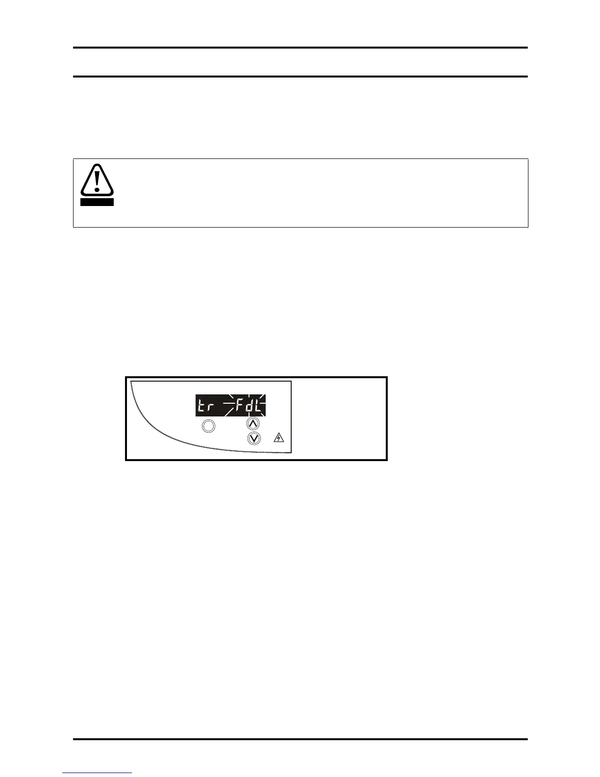
The FXMP25 display shows an FdL trip on the display as shown in Figure 9-1 below:
Figure 9-1 Typical example of trip display
The above graphic shows the resultant display following an FdL trip. This indicates a
field loss condition as described in Table 9-1 on page 61 overleaf.
Users must not attempt to repair a faulty FXMP25 or carry out fault diagnosis other than
replace internal fuses or through the use of the diagnostic features described in this
chapter. Under no circumstances must the casing of the FXMP25 be opened when the
AC supply is connected. Faulty units must be returned to an authorized Control
Techniques distributor for repair.
M
STORED CHARGE
10 min
Mode /Reset
FXMP25
FXMP25 status
= tripped
Trip type
(FdL =Field loss)

 Loading...