6
Supplied Accessories
Owner's Manual Quick Start Guide Registration card
Remote Control
(NH001UD)
Batteries
(AAA, 1.SV x 2)
TV base and 6 screws (MS x 12)
AC power cord
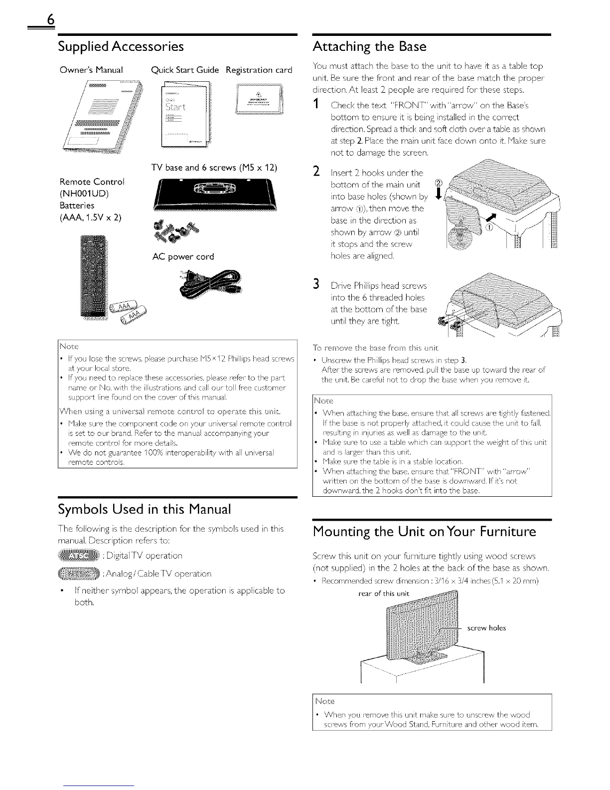
Attaching the Base
You must attach the base to the unt to have it as a table top
unit. Be sure the front and rear of the base match the proper
direction, At least 2 people are requ red for these steps.
1 Check the text "FRONT" w_th "an ow" on the Base's
bottom to ensure t is being installed n the correct
direct on. Spread a thd< and soft cloth over a table as shown
at step 2. Place the man unit face down onto it. Make sure
not to damage the screen.
_- Insert 2 hooks under the ....
(2)
bottom of the main unt .......
into base holes (shown by 1_ _
an'ow Q)), then move the
base nthe drecton as
shown by an'ow ,12)until
¢ stops and the screw
holes are aigned.
3 Drve Ph Ilips head screws
into the 6 threaded holes
at the bottom of the base
until they are tght
Nop
If you lose the screws, please purchase bi5 x 12 Ph ps head screws
at your Ioca store,
If you need to replace these accessories, please refer to the part
name or No. with the lustlations and call our toll flee cu£orner
support Ine foupd on the cover of this manual,
V_el ss£ a unve_sa _e_o e ecxl _o o opelate rhs _s/:,
blal<e sure the component code on your universa i emote control
s set to our brand, Re@r to the mar, ua accompanying your
remote contro for more dora s.
We do not guarantee 100% nteroperability wth all universal
remote contro s,
Symbols Used in this Manual
[he following s the descr ption for the symbols used n ths
manual. Description refers to:
:D gitalJV operat on
:Analog/Cable rv operation
If neither symbol appears, the operation s applicable to
both.
[o _ , hove the base fort ds *r/t
• Unscrew the Phillips head screws in step 3,
After the screws are removed, pull the base up toward the rear of
the unit, Be ca1_'fu not to drop the base when you remove It,
Not_,
When attaching the base, ensure that all solews am tightly fastened,
If the base is not properly art ched, it could cause the unt to fal,
resulting in injuries as well as damage to the unit.
blsl<e sure to use a tabe whch can support the weight ofths unit
and s arger than this unt.
blal<e sure the table is in a stable location,
When attaching the base, ensure that"FRONT" wth "arrow"
written on the bottom of the base is dowr,wald, If t's not
downward, the _ hooks don't fit into the base,
Mounting the Unit onYour Furniture
Screw this unt on your furnture t ghtiy using wood screws
(not supplied) in the 3=holes atthe bad< of the base as shown.
• Recommended screw dimens on :3/16 x 3/4 nches(5,1 x _0 ram)
rear of this unit
screw holes
 Loading...