CAUTION
Wrong supply voltage! Material damage! Never use power that differs from
that indicated as it could damage the controller. Always use safety
transformers.
▪ PeC C100: 24 VAC ± 10 %, 50/60 Hz (consumption 25 VA) for the version with one EEV.
▪ PeC C200: 24 VAC ± 10 %, 50/60 Hz (consumption 50 VA) for the version with 2 EEV.
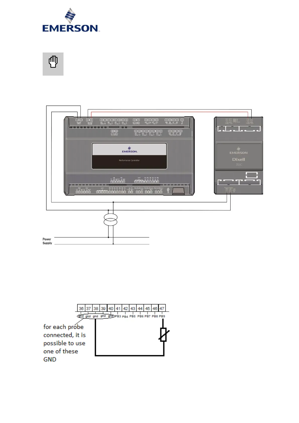
4.2.2 Power supply voltage with battery backup
Figure 11
4.3 Connection of the analog inputs
4.3.1 Temperature probes (NTC)
Each sensor must be connected through one of the inputs (from PB3 to PB9) and the common (Com)
as shown in the diagram in Figure 12 below. Refer to Tables 3 & 10 for the numbering.
The 2-wire sensor does not require polarity to be respected.
Figure 12: Temperature probes connection

 Loading...


