AGL_Sol_PEC_01_E_Rev01 19
4.3.2 Pressure transducers and current probes (4-20 mA)
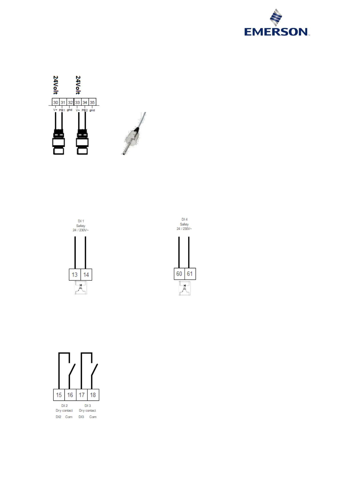
Two sensors must be connected through one of the inputs (from PB1 to PB2) and the power supply as
shown in the diagram in Figure 13 below. Refer to Tables 3 & 10 for the numbering.
The 2-wire sensors require polarity to be respected (+24 VDC power supply).
Figure 13
4.4 Connection of the digital inputs
The digital inputs in the PeC controllers can be used as potential free digital inputs.
4.4.1 Opto-insulated digital inputs (24-230 VAC/DC) DI1 and DI4
Refer to diagrams in Figures 14 & 15 below and to Tables 3 & 10 for the numbering.
Figure 14: Digital inputs PeC C100 Figure 15: Digital inputs PeC C200
NOTE: For A2L and A3 applications use 24 volts.
4.4.2 Potential free digital input DI2 and DI3
Refer to diagram in Figure 16 below and to Tables 3 & 10 for the numbering.
The function is determined by the configuration (currently not in use).
Figure 16: Digital inputs PeC C100 & C200

 Loading...


