26 • XR75CX I&O Manual 026-1210 Rev 0 09-FEB-2011
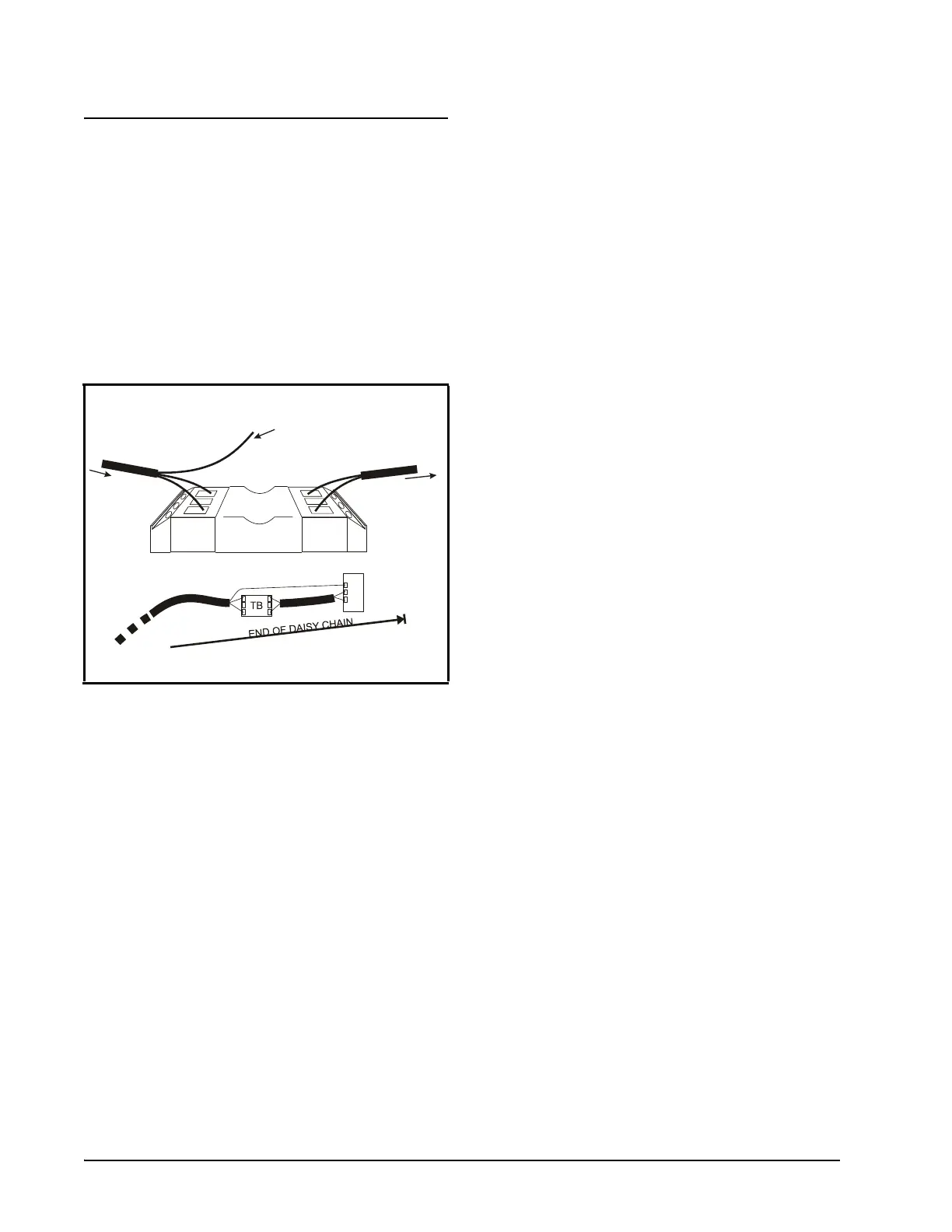
18.3.MODBUS Termination
Blocks
Because the XR75CX device has no on-board
means of termination, use the MODBUS termination
block (P/N 535-2711) for termination that can be
wired to the end of the cable segment using the three-
pin connector. Wire the two signal wires to the out-
side terminals, and connect the shield to pin 18 of the
device, keeping the exposed shield wire length as
short as possible (3 inches ideal maximum length).
Figure 18-8 - MODBUS Termination Block (P/N 535-2711)
SHIELD WIRE
(CONNECT TO
OF LAST DEVICE)
PIN 18
FROM OTHER
DEVICES
TO LAST DEVICE
AT END OF DAISY
CHAIN
 Loading...