Frontier Oil Heat – PN 10-2021 – October 2021 - 10 -
OIL BURNER SETTINGS
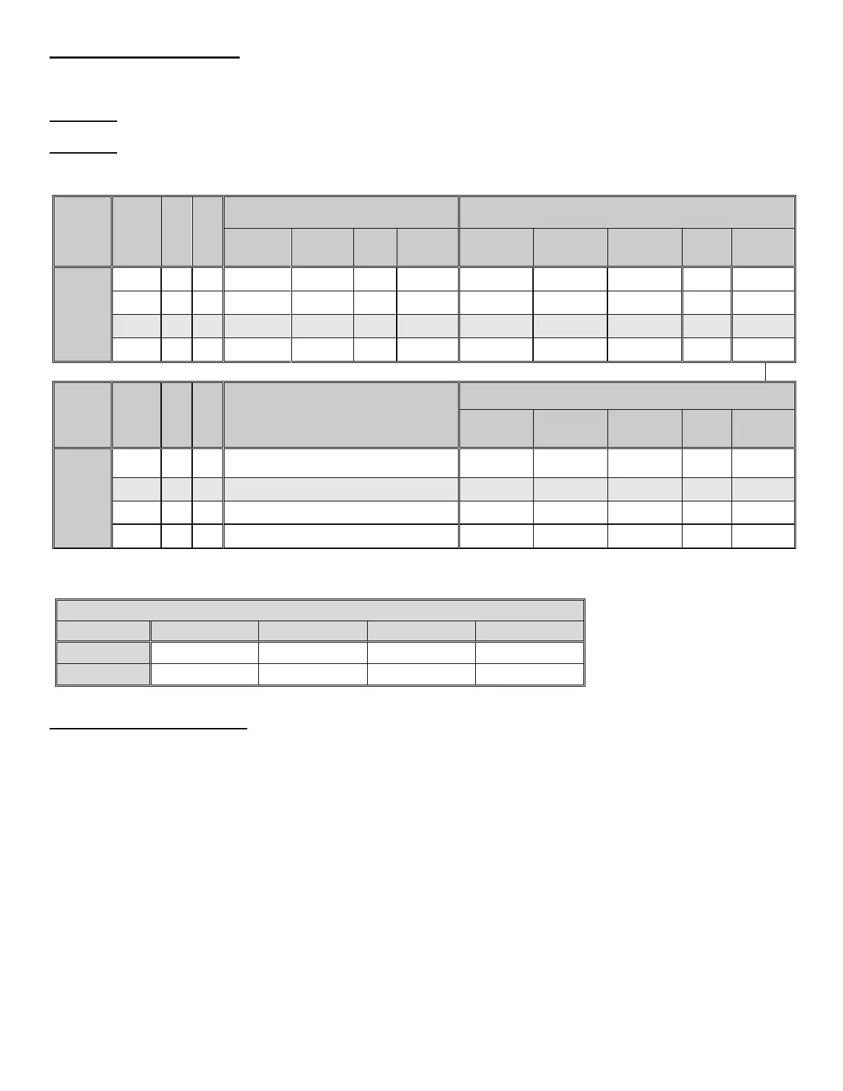
EK1 Boilers are shipped from the factory preset for 0.85 GPH firing rate and EK2 Boilers are shipped from the factory
preset for 1.40 GPH firing rate. The SYSTEM 2000 Boiler can be fired over a range of firing rates to suit the needs of the
application. The following table lists approximate settings for oil burners based on testing performed at Energy Kinetics.
CAUTION: Final settings for each burner and firing rate for a particular installation must be determined by using
combustion test equipment and following the instructions given under "Start Up Procedure".
CAUTION: Because the energy converter removes heat from the combustion flue gas so efficiently, low firing rates may
not provide high enough flue gas temperature for proper draft in a chimney. The Columns labeled 'Chimney' and
'Sidewall' show the suitability of the firing rate for a particular combination.
1
the Beckett AFG at 0.68 gph firing rate can be retrofitted with the Beckett Low Firing Rate Baffle. If used, set air band: 0, shutter: 8.5.
* Factory Setting
** Head Setting on Carlin EZ-1 set by using supplied Head Bars
Optional Nozzle Equivalents
Optional Nozzles for Carlin EZ-1-HP
OIL BURNER MOUNTING
SYSTEM 2000 Boilers are shipped from the factory with the oil burner pre-mounted. The burner flanges are designed
to insert the burner head 2-3/8” into the boiler. Energy Kinetics installs a ceramic sleeve, (the amulet), to protect the
burner head from the heat of combustion, and then seals the air tube flange joint with a high grade retort cement.
NOTICE: Oil burners for field installation or for field replacement should be installed according to burner manufacturer
instructions, according to installation instructions below, and with consultation with Energy Kinetics for any special
considerations or adjustments.
Follow these instructions for field installation of Energy Kinetics supplied burners. Start by checking nozzle and
electrode position per manufacturer’s specifications prior to assembly to unit. Test fit the amulet by inserting the amulet
into the boiler opening. If the amulet doesn't easily slide into the boiler, then gently sand the outside diameter of the
amulet until it will fit into the boiler opening. Test fit the amulet onto the burner head. Note that the amulet designed with
interior slots to accept the screws on the sides of the head on Beckett AFG burners. The amulet has a small drain hole in
the front face, which must be mounted at the bottom (at 6 o'clock position). If the amulet is a tight fit on the burner head,
then slightly moisten inside the amulet with water.
Place a 3/8" bead of retort cement onto the burner head at the flange to air tube joint, and slide the (moistened)
amulet over the burner head and against the flange. Ensure proper seating of the amulet by pressing the amulet onto the
burner with a flat object. Leave the excess retort cement at the amulet to flange joint and the cement will provide an
airtight seal of the air tube flange to the boiler face.
 Loading...


