Frontier Oil Heat – PN 10-2021 – October 2021 - 16 -
LOW VOLTAGE WIRING
ENERGY MANAGER OPERATES ONLY ON 24 VOLTS 60 HZ POWER
WARNING: Make All Connections with Power Off at Main Circuit Box
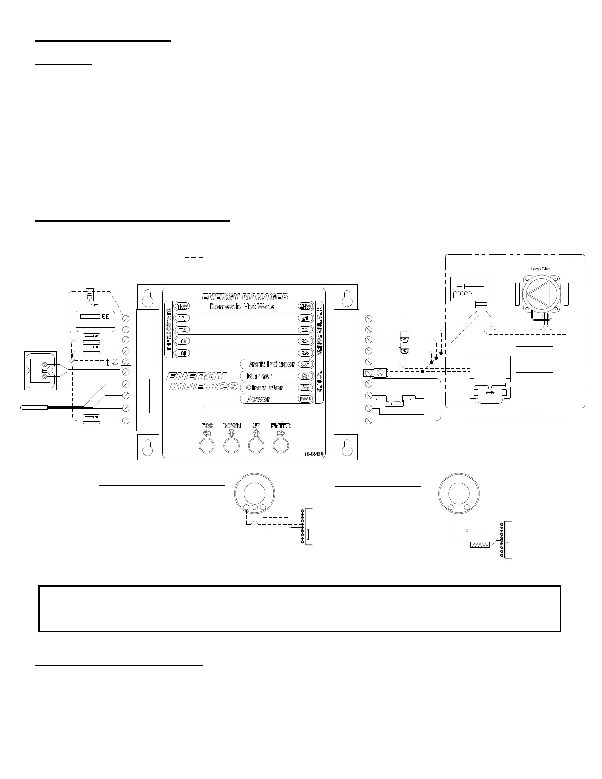
A typical low voltage wiring diagram for the Energy Manager is shown in Figure 4A. Thermostats must be
located on inside walls away from cold drafts, windows or heat from fireplaces, appliances or sunlight. Set thermostat
heat anticipators to 0.1 amps (or "gas" if gas/electric option). Call Energy Kinetics to request alternate low voltage wiring
diagrams to handle special situations such as air handler wiring, heat pump wiring, isolation relays for thermostats, and
isolation relays for heat motors or circulators, etc.
The single 24-volt/50VA transformer is suitable for the Energy Manager and five zone outputs (zone valves or
relays). NOTICE: Additional load such as extra valves may require greater transformer capacity. To add transformers,
wire in parallel as follows: wire terminal “A” on one transformer to “A” on the other. Repeat with other low voltage terminal
“B”. Be sure to verify 24VAC output from all transformers.
The Energy Manager is designed to heat domestic water and up to four (4) heating zones. Use Energy Kinetics
supplied zone valves with two wire connections. For more than four heating zones, use Energy Kinetics 15 zone
expanded Energy Manager, or call Energy Kinetics for alternatives.
LOW VOLTAGE WIRING DIAGRAM
INSTALL ENERGY MANAGER
The Energy Manager is shipped in its own protective shipping box. NOTICE: The option switches can be set very
easily before the Manager is installed. Locate the pre-wired quick connectors fastened to the front of the junction box by
two cable ties. Cut the two cable ties and discard. Fasten the Energy Manager to the junction box with the four corner
screws. Slide the two quick connectors onto the Energy Manager. Label each zone on the manager, using the adhesive
labels supplied.
TEMP. SENS.
RED
WHITE
R
S
BLACK
B
A2
A1
B2
CIRC
B1
MAIN CIRC RELAY
24VAC
IND
ZONE 2
ZONE 1
HOT WATER TANK
ZONE 1
ZONE 2
ZONE 4
LOAD
A
B
Thermistor or
Digital Sensor
(Located in Boiler
Return Piping)
T3
T1
T2
THW
T4
Z1
Z2
Z3
Z4
ZHW
HOT WATER CIRC RELAY
ZONE 3
or ADDITIONAL ZONE
ZONE 3
ZONE 4
Transformer
24VAC 50VA
T2
T4
A2
S
TEMP. SENS.
R
B
A1
T3
THW
T1
Tx*
CR
W
T2
T4
A2
S
TEMP. SENS.
R
B
A1
T3
THW
T1
Tx*
Resistor between
A2 and Tx
POWER STEALING OR WIFI THERMOSTATS THAT
REQUIRE A COMMON
CONNECT THE COMMON OR C TERMINAL ON THE
THERMOSTAT TO THE A2 TERMINAL ON THE
MANAGER
*Tx CAN BE T1, T2, T3, T4 OR EVEN THW IF USED AS A
HEATING ZONE
POWER STEALING THERMOSTAT
USING 2 WIRES
USING 15 WATT 200 OHM RESISTOR
(OR ISOLATE FROM MANAGER WITH A RELAY)
*Tx CAN BE T1, T2, T3, T4 OR EVEN THW IF
USED AS A HEATING ZONE
R
W
FIELD WIRING
FACTORY WIRING
*Field Wiring terminated to input terminal A1 and to output terminal 24VAC are to
be wired into the open lugs provided at those locations.
NOTE: ALL ENERGY DISPLAY MANAGERS (W/LCD DISPLAY} ARE DESIGNED TO WORK WITH NEST THERMOSTATS WIRED DIRECT USING ONLY 2 WIRES
Injection Zone
Valve
ZONE 3
Loop Circ Relay
Connected to Z11
ZONE 4
N
L1
WHEN SECONDARY ZONES ARE ENABLED
(PRIMARY/SECONDARY PIPING)
ZONE 3 BECOME THE INJECTION ZONE
ZONE 4 BECOMES THE LOOP CIRC
STACK LIMIT
T
T
TO BURNER
RELAY
Note: Many WiFi thermostats require a common (c) wire, including some Nest models. C on the thermostat
can be wired to A2 on the Energy Manager. This, in addition to R on the thermostat being wired to
A1 on the Energy Manager will provide the 24 volts needed for the thermostat to operate.
 Loading...


