Frontier Oil Heat – PN 10-2021 – October 2021 - 19 -
EXPANDED ENERGY MANAGER
15 ZONE MANAGER INSTALLATION INSTRUCTIONS
1. Remove cover from junction box.
Use a free knockout on the top of the junction box to mount a second or third transformer, wire black lead to “XFMR”
and white lead to “NEUTRAL” on relay board in box. (Use sections marked “120 VOLTS” only.) A second junction
box is not needed for the expanded Energy Manager. Wire additional transformer(s) in parallel with first transformer.
To wire in parallel, wire terminal “A” on one transformer to “A” on the other. Repeat with other low voltage terminal
“B”. Verify 24VAC output from all transformers BEFORE reconnecting the Manager.
2. Mount long panel on top of box cover with long screws provided in lower 4 holes with spacers down.
3. Mount expanded Energy Manager to cover plate over 4 long screws and 2 wide bolts (top 2 holes).
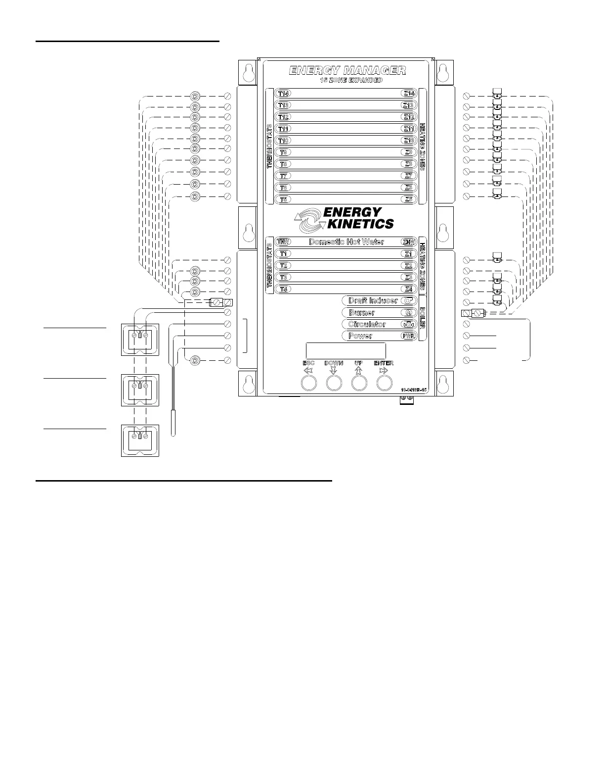
4. Wire the bottom half of expanded manager as 5 zones Energy Manager. For top half, attach one thermostat lead to a
zone and the other to A1 on lower half of manager. Attach one lead from zone valve or relay to corresponding zone
output and the other lead to 24VAC on lower half.
5. Option switches set fuel type (oil or gas) and venting (chimney or power vented).
See Location of Switches: Figure. 4B.
6. NOTE: When using secondary zones with 15-zone manager, zone 13 controls injection zone, and zone 14 controls
loop circulator.
NOTICE: When operating without an expanded manager, use a 5 zone service board for the lower half. If you do not
have a service board, refer to “Operation of Boilers without Energy Manager” in the Tech Manual.
15 Zone Manager
Figure 4C
®
T9
TEMP. SENS.
RED
SILVER
R
S
BLACK
B
A2
A1
T11
T10
B2
CIRC
B1
T
MAIN CIRC RELAY
T
TO BURNER RELAY
24VAC
IND
ZONE 2
Z11
ZONE 1
ZONE 4
ZONE 9
ZONE 11
ZONE 10
T8
T7
T6
T5
THW
T1
T2
T3
Z10
Z9
Z8
Z7
Z6
Z5
Z4
ZHW
Z1
Z2
ZONE 8
ZONE 7
ZONE 6
ZONE 5
ZONE 1
ZONE 2
ZONE 3
ZONE 11
ZONE 10
ZONE 9
ZONE 8
ZONE 7
ZONE 6
ZONE 5
HW CIRC RELAY
ZONE INPUTS
(THERMOSTATS)
ZONE OUTPUTS
24VAC
(ZONE VALVES OR
ZONE CIRC RELAYS)
LOAD
A
B
LOAD
A
B
TRANSFORMER 1
24VAC (50VA)
(FACTORY WIRED)
Handles first five zones.
TRANSFORMER 2
24VAC (50VA)
(FIELD INSTALLED)
Handles up to ten zones.
LOAD
A
B
TRANSFORMER 3
24VAC (50VA)
(FIELD INSTALLED)
Handles up to 15 zones
T4
Z3
T12
T13
T14
Z12
Z13
Z14
ZONE 4
HOT WATER TANK
ZONE 12
ZONE 13
ZONE 14
ZONE 3
ZONE 12
ZONE 13
ZONE 14
 Loading...


