Frontier Oil Heat – PN 10-2021 – October 2021 - 32 -
REPLACEMENT PARTS
To order replacement parts, specify serial number
stamped onto nameplate, part description and part number
from parts list and assembly drawing on the next page.
AMULET REPLACEMENT
It is recommended that a new ceramic sleeve “amulet” be
installed each time the air tube is removed from unit. See
instructions that come with each amulet. The Frontier
amulet is larger than the standard amulet, so be sure to
order the proper part number shown in the Assembly
Drawing. Using a standard amulet will allow excessive heat
back to the front jacket and may damage burner tube.
COMBUSTION CHAMBER REPLACEMENT
The combustion chamber is of high quality refractory ceramic fiber material and will normally not need to be replaced. A
replacement chamber, if required, is available from Energy Kinetics. The proper part number for the Frontier chamber
must be specified when ordering. For interim operation, the unit may be run without a combustion chamber if necessary.
Ensure that the burner head is protected by the amulet, wet pack or a similar material.
To install the replacement. CAUTION: A dust mask must be worn during procedure:
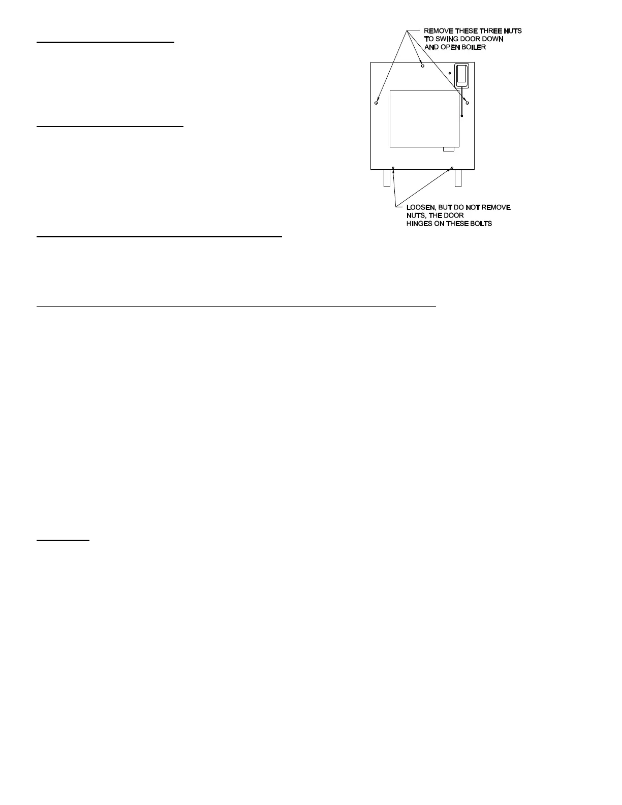
1. Open boiler by removing the nuts on the top center, middle left and right of the boiler. Note: Loosen, but do not
remove, the two 3/8” nuts on the bottom of the front jacket, the door is hinged upon these bolts (See Fig.7).
While supporting the door, lower door slowly to the down position.
2. Spray chamber with a water mist to minimize disturbance and breakage of chamber material.
3. Remove chamber by tilting upward and rotating to loosen.
4. Locate and inspect the square dimple in the rear insulation board. The lower side of the chamber will insert into
this dimple.
5. Locate the 4”x2” support molded on the backside of the chamber and coat the 2” sides with refractory cement.
6. Insert chamber into the boiler with the exhaust opening in the 3 o’clock position. Chamber outlet must fit behind
or alongside the metal tab (supply nipple) in the top rear of the boiler.
7. With chamber fully inserted, slightly move the chamber until the chamber outlet is snug against the right side of
the boiler. The 4”x2” support on the back of the chamber should fit securely into the dimple on the rear insulation
board.
8. Verify that the chamber is centered and ensure that the burner is centered with the chamber when closing the
front door. Secure and tighten the three nuts. Also, check the two 3/8” nuts on the lower hinge bolts and ensure
that they are tight. Do not over tighten; tighten snugly enough to compress the door insulation.
9. Confirm proper setup and operation of burner (see "Oil Burner Operation").
WARNING: Ceramic fiber or fiberglass materials may contain carcinogenic particles (cristobalite) after exposure to heat.
Airborne particles from fiberglass or ceramic fiber components have been listed as having potential health effects. Take
the following precautions when removing, replacing and handling these items.
Precautionary procedures:
Avoid breathing dust and avoid contact with skin or eyes. Wear long-sleeved, loose-fitting clothing, gloves and eye
protection. Use a properly fitted NIOSH certified respirator for dusty activities and where exposure levels are unknown.
Use hand tools whenever possible if cutting or trimming is required. Power tools generate significantly more airborne
dust.
Use vacuums with HEPA-filters for clean up. If HEPA-filter vacuum are not feasible, lightly spray fiber materials and
work area with a water mist before sweeping or bagging of debris.
Wash exposed skin with soap and water after handling.
Do not use compressed air to clean work clothes or work area.
Wash work clothes separately from other clothing. Rinse washer thoroughly afterwards.
Avoid smoking, eating or drinking while dust is present in the work area.
 Loading...


